Note
Hello, welcome to the SunFounder Raspberry Pi & Arduino & ESP32 Enthusiasts Community on Facebook! Dive deeper into Raspberry Pi, Arduino, and ESP32 with fellow enthusiasts.
Why Join?
Expert Support: Solve post-sale issues and technical challenges with help from our community and team.
Learn & Share: Exchange tips and tutorials to enhance your skills.
Exclusive Previews: Get early access to new product announcements and sneak peeks.
Special Discounts: Enjoy exclusive discounts on our newest products.
Festive Promotions and Giveaways: Take part in giveaways and holiday promotions.
👉 Ready to explore and create with us? Click [here] and join today!
2.2.2 Thermistor(MCP3008)
Note

Depending on your kit version, please identify whether you have ADC0834 or MCP3008 and proceed with the matching section.
Introduction
Just like photoresistor can sense light, thermistor is a temperature sensitive electronic device that can be used for realizing functions of temperature control, such as making a heat alarm.
Required Components
In this project, we need the following components.
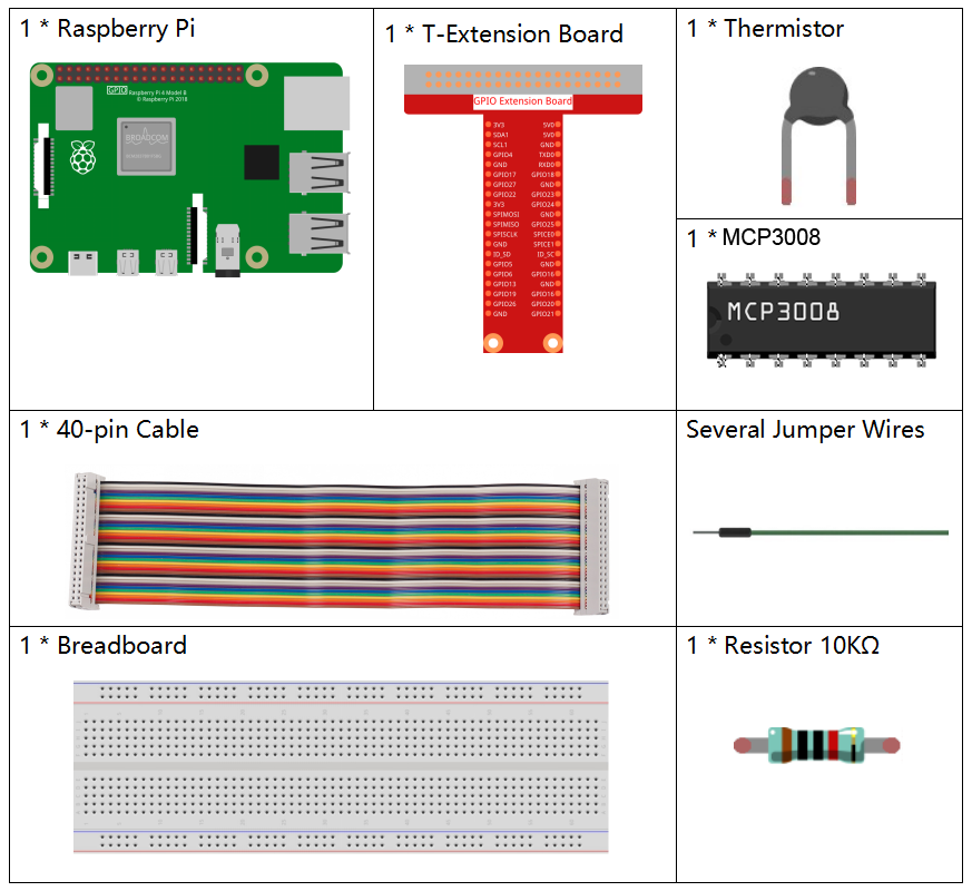
It’s definitely convenient to buy a whole kit, here’s the link:
Name |
ITEMS IN THIS KIT |
LINK |
|---|---|---|
Raphael Kit |
337 |
You can also buy them separately from the links below.
COMPONENT INTRODUCTION |
PURCHASE LINK |
|---|---|
- |
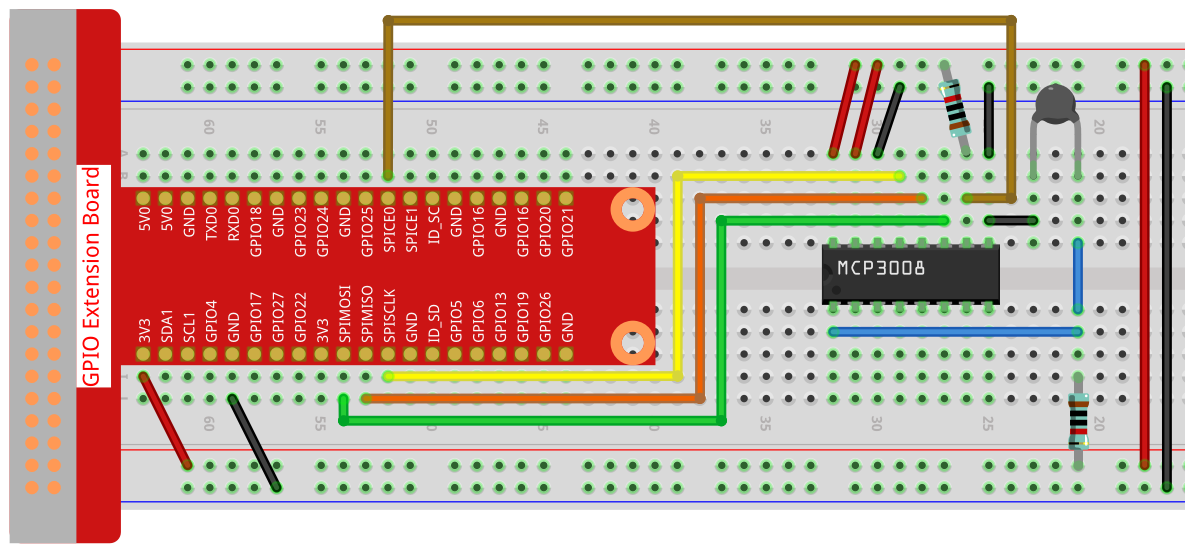
Schematic Diagram
T-Board Name |
physical |
WiringPi |
BCM |
|---|---|---|---|
SPICE0 |
pin24 |
10 |
8 |
SPIMOSI |
pin19 |
12 |
10 |
SPIMISO |
pin21 |
13 |
9 |
SPISCLK |
pin23 |
14 |
11 |

Experimental Procedures
Step 1: Build the circuit.
Step 2: Go to the folder of the code.
cd ~/raphael-kit/c/2.2.2-2/
Step 3: Compile the code.
gcc 2.2.2_Thermistor.c -o Thermistor -lwiringPi -lm
Note
-lm is to load the library math. Do not omit, or you will make an error.
Step 4: Run the executable file.
./Thermistor
With the code run, the thermistor detects ambient temperature which will be printed on the screen once it finishes the program calculation.
Note
If it does not work after running, or there is an error prompt: "wiringPi.h: No such file or directory", please refer to Install and Check the WiringPi.
Code
#include <wiringPi.h>
#include <wiringPiSPI.h>
#include <stdio.h>
#include <math.h>

#define SPI_CHANNEL 0  // CE0
#define SPI_SPEED   1000000  // 1MHz

int read_ADC(int channel) {
    if (channel < 0 || channel > 7) return -1;

    unsigned char buffer[3];
    buffer[0] = 1;  // Start bit
    buffer[1] = (8 + channel) << 4;  // Single-ended mode + channel
    buffer[2] = 0;

    wiringPiSPIDataRW(SPI_CHANNEL, buffer, 3);

    int value = ((buffer[1] & 3) << 8) | buffer[2];
    return value;
}

int main(void) {
    int analogVal;
    double Vr, Rt, temp, cel, Fah;

    if (wiringPiSetup() == -1) {
        printf("setup wiringPi failed!\n");
        return 1;
    }

    if (wiringPiSPISetup(SPI_CHANNEL, SPI_SPEED) == -1) {
        printf("SPI setup failed!\n");
        return 1;
    }

    while (1) {
        analogVal = read_ADC(0);  // Read from CH0

        // MCP3008 is 10-bit ADC (0–1023)
        Vr = 3.3 * analogVal / 1023.0;  // Assume Vref = 3.3V
        Rt = 10000.0 * Vr / (3.3 - Vr); // Voltage divider, 10k resistor
        temp = 1 / ((log(Rt / 10000.0) / 3950.0) + (1 / (273.15 + 25.0)));
        cel = temp - 273.15;
        Fah = cel * 1.8 + 32;

        printf("Celsius: %.2f C  Fahrenheit: %.2f F\n", cel, Fah);
        delay(1000);
    }

    return 0;
}
Code Explanation
#include <wiringPi.h>
#include <wiringPiSPI.h>
#include <stdio.h>
#include <math.h>
These header files include libraries for GPIO control (wiringPi.h), SPI communication (wiringPiSPI.h), standard I/O operations (stdio.h), and math functions (math.h) in C.
#define SPI_CHANNEL 0
#define SPI_SPEED   1000000
Define constants for the SPI channel and SPI communication speed. Here, SPI channel 0 (CE0) and a clock speed of 1 MHz are used.
int read_ADC(int channel)
This function reads analog data from a specified channel of the MCP3008 ADC.
buffer[0] = 1;
buffer[1] = (8 + channel) << 4;
buffer[2] = 0;
These lines format the SPI command according to the MCP3008 protocol: a start bit, configuration for single-ended mode, and the channel number.
wiringPiSPIDataRW(SPI_CHANNEL, buffer, 3);
Transfer the SPI command and receive the 10-bit ADC data from MCP3008.
int value = ((buffer[1] & 3) << 8) | buffer[2];
Extract and combine the 10-bit ADC result from the returned SPI buffer.
if (wiringPiSetup() == -1) { ... }
if (wiringPiSPISetup(SPI_CHANNEL, SPI_SPEED) == -1) { ... }
These lines initialize WiringPi and configure SPI. If initialization fails, the program exits.
analogVal = read_ADC(0);
Reads the analog signal from MCP3008 channel 0, where the thermistor voltage divider is connected.
Vr = 3.3 * analogVal / 1023.0;
Convert the digital ADC value into an analog voltage. The ADC range is 0–1023 with 3.3V reference voltage.
Rt = 10000.0 * Vr / (3.3 - Vr);
Calculate the resistance of the thermistor using the voltage divider formula. A 10kΩ resistor is assumed in series with the thermistor.
temp = 1 / ((log(Rt / 10000.0) / 3950.0) + (1 / (273.15 + 25.0)));
Use the B-parameter equation to convert the thermistor resistance to temperature in Kelvin.
T(K) = 1 / [ln(Rt/R₀)/B + 1/T₀], where - R₀ = 10kΩ - B = 3950 - T₀ = 25°C = 298.15K
cel = temp - 273.15;
Convert the temperature from Kelvin to degrees Celsius.
Fah = cel * 1.8 + 32;
Convert the Celsius temperature to Fahrenheit.
printf("Celsius: %.2f C Fahrenheit: %.2f F\n", cel, Fah);
Display the temperature in both Celsius and Fahrenheit on the terminal with 2 decimal places of precision.