1.1.6 LED Dot Matrix Module
Introduction
In this project, you will learn about LED Matrix Module. LED Matrix Module uses the MAX7219 driver to drive the 8 x 8 LED Matrix.
Required Components
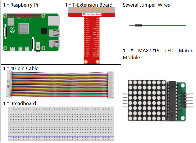
In this project, we need the following components.

It’s definitely convenient to buy a whole kit, here’s the link:
Name |
ITEMS IN THIS KIT |
LINK |
|---|---|---|
Raphael Kit |
337 |
You can also buy them separately from the links below.
COMPONENT INTRODUCTION |
PURCHASE LINK |
|---|---|
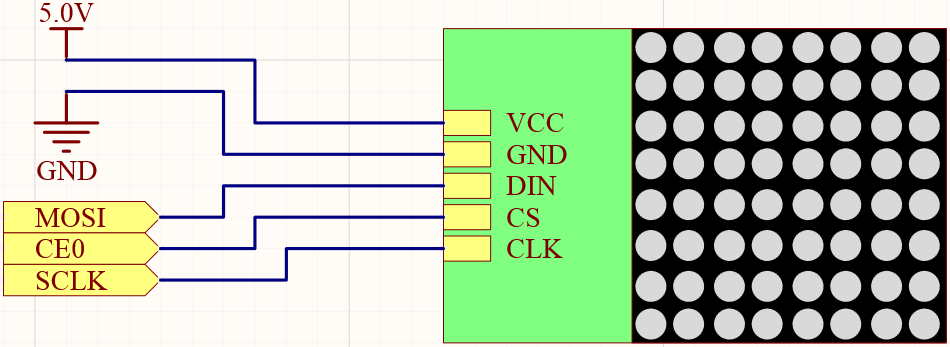
Schematic Diagram
T-Board Name |
physical |
wiringPi |
BCM |
SPIMOSI |
Pin 19 |
12 |
MOSI |
SPICE0 |
pin 24 |
10 |
CE0 |
SPISCLK |
Pin 23 |
14 |
SCLK |

Experimental Procedures
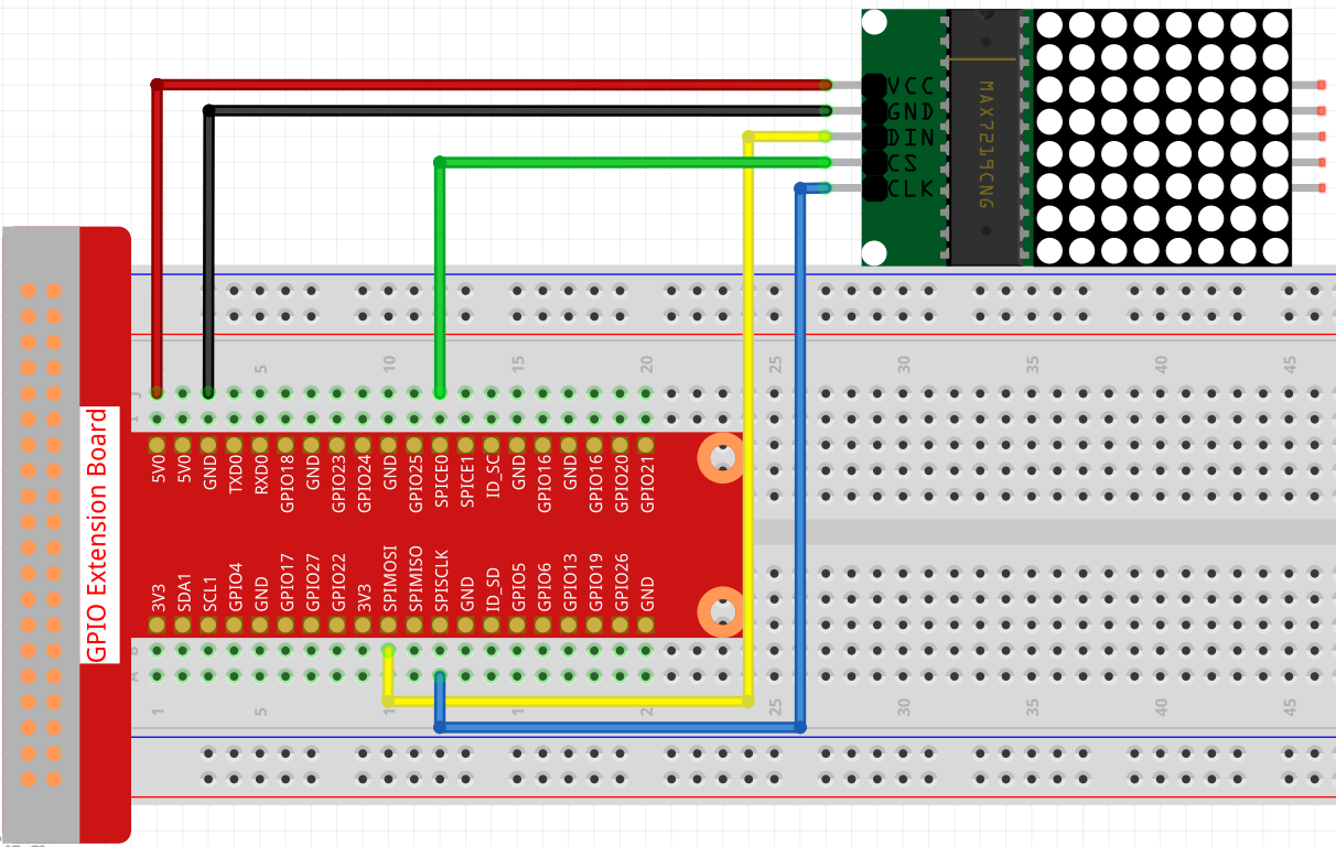
Step 1: Build the circuit.

Note
Turn on the SPI before starting the experiment, refer to SPI Configuration for details. And the BCM2835 library is also needed.
Step 2: Go to the folder of the code.
cd ~/raphael-kit/c/1.1.6/
Step 3: Compile the code.
make
Step 4:: Run the executable file.
sudo ./1.1.6_LedMatrix
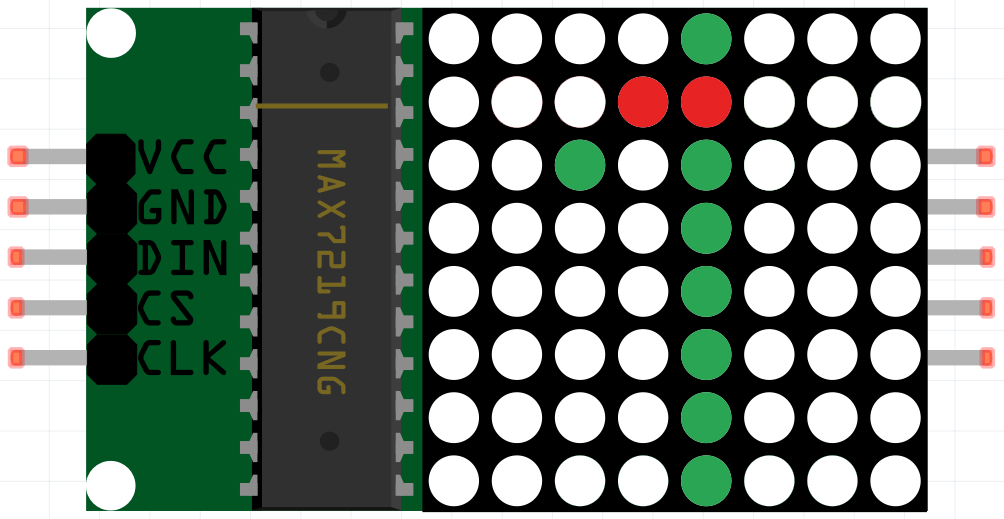
After running the code, the LED Dot Matrix displays from 0 to 9 and A to Z in sequence.
Note
If it does not work after running, or there is an error prompt: "wiringPi.h: No such file or directory", please refer to Install and Check the WiringPi.
Code
#include <bcm2835.h>
#include <stdio.h>
#include <string.h>
#include <ctype.h>

#define uchar unsigned char
#define uint unsigned int

#define Max7219_pinCS  RPI_GPIO_P1_24

uchar disp1[36][8]={
{0x3C,0x42,0x42,0x42,0x42,0x42,0x42,0x3C},//0
{0x08,0x18,0x28,0x08,0x08,0x08,0x08,0x08},//1
{0x7E,0x2,0x2,0x7E,0x40,0x40,0x40,0x7E},//2
{0x3E,0x2,0x2,0x3E,0x2,0x2,0x3E,0x0},//3
{0x8,0x18,0x28,0x48,0xFE,0x8,0x8,0x8},//4
{0x3C,0x20,0x20,0x3C,0x4,0x4,0x3C,0x0},//5
{0x3C,0x20,0x20,0x3C,0x24,0x24,0x3C,0x0},//6
{0x3E,0x22,0x4,0x8,0x8,0x8,0x8,0x8},//7
{0x0,0x3E,0x22,0x22,0x3E,0x22,0x22,0x3E},//8
{0x3E,0x22,0x22,0x3E,0x2,0x2,0x2,0x3E},//9
{0x8,0x14,0x22,0x3E,0x22,0x22,0x22,0x22},//A
{0x3C,0x22,0x22,0x3E,0x22,0x22,0x3C,0x0},//B
{0x3C,0x40,0x40,0x40,0x40,0x40,0x3C,0x0},//C
{0x7C,0x42,0x42,0x42,0x42,0x42,0x7C,0x0},//D
{0x7C,0x40,0x40,0x7C,0x40,0x40,0x40,0x7C},//E
{0x7C,0x40,0x40,0x7C,0x40,0x40,0x40,0x40},//F
{0x3C,0x40,0x40,0x40,0x40,0x44,0x44,0x3C},//G
{0x44,0x44,0x44,0x7C,0x44,0x44,0x44,0x44},//H
{0x7C,0x10,0x10,0x10,0x10,0x10,0x10,0x7C},//I
{0x3C,0x8,0x8,0x8,0x8,0x8,0x48,0x30},//J
{0x0,0x24,0x28,0x30,0x20,0x30,0x28,0x24},//K
{0x40,0x40,0x40,0x40,0x40,0x40,0x40,0x7C},//L
{0x81,0xC3,0xA5,0x99,0x81,0x81,0x81,0x81},//M
{0x0,0x42,0x62,0x52,0x4A,0x46,0x42,0x0},//N
{0x3C,0x42,0x42,0x42,0x42,0x42,0x42,0x3C},//O
{0x3C,0x22,0x22,0x22,0x3C,0x20,0x20,0x20},//P
{0x1C,0x22,0x22,0x22,0x22,0x26,0x22,0x1D},//Q
{0x3C,0x22,0x22,0x22,0x3C,0x24,0x22,0x21},//R
{0x0,0x1E,0x20,0x20,0x3E,0x2,0x2,0x3C},//S
{0x0,0x3E,0x8,0x8,0x8,0x8,0x8,0x8},//T
{0x42,0x42,0x42,0x42,0x42,0x42,0x22,0x1C},//U
{0x42,0x42,0x42,0x42,0x42,0x42,0x24,0x18},//V
{0x0,0x49,0x49,0x49,0x49,0x2A,0x1C,0x0},//W
{0x0,0x41,0x22,0x14,0x8,0x14,0x22,0x41},//X
{0x41,0x22,0x14,0x8,0x8,0x8,0x8,0x8},//Y
{0x0,0x7F,0x2,0x4,0x8,0x10,0x20,0x7F},//Z
};

void Delay_xms(uint x)
{
    bcm2835_delay(x);
}
//------------------------

void Write_Max7219_byte(uchar DATA)
{
    bcm2835_gpio_write(Max7219_pinCS,LOW);
    bcm2835_spi_transfer(DATA);
}

void Write_Max7219(uchar address1,uchar dat1)
{
    bcm2835_gpio_write(Max7219_pinCS,LOW);
    Write_Max7219_byte(address1);
    Write_Max7219_byte(dat1);
    bcm2835_gpio_write(Max7219_pinCS,HIGH);
}

void Init_MAX7219()
{
    Write_Max7219(0x09,0x00);
    Write_Max7219(0x0a,0x03);
    Write_Max7219(0x0b,0x07);
    Write_Max7219(0x0c,0x01);
    Write_Max7219(0x0f,0x00);
}

void Init_BCM2835()
{
    bcm2835_spi_begin();
    bcm2835_spi_setBitOrder(BCM2835_SPI_BIT_ORDER_MSBFIRST);
    bcm2835_spi_setDataMode(BCM2835_SPI_MODE0);
    bcm2835_spi_setClockDivider(BCM2835_SPI_CLOCK_DIVIDER_256);
    bcm2835_gpio_fsel(Max7219_pinCS, BCM2835_GPIO_FSEL_OUTP);
    bcm2835_gpio_write(disp1[0][0],HIGH);
}

int main(void)
{
    uchar i,j;

    if (!bcm2835_init())
    {
        printf("Unable to init bcm2835.\n");
        return 1;
    }
    Init_BCM2835();
    Delay_xms(50);
    Init_MAX7219();
    while(1)
    {
        for(j=0;j<36;j++)
        {
            for(i=1;i<9;i++)
            {
                Write_Max7219(i,disp1[j][i-1]);
            }
            Delay_xms(1000);
        }
    }
    // bcm2835_spi_end();
    // bcm2835_close();
    return 0;
}
Code Explanation
#define Max7219_pinCS 24
The cs pin of the LED Dot Matrix is connected to pin24.
Note
When you have multiple devices that need spi communication, just connect the cs pins on different pins.
if (!bcm2835_init())
    {
            printf("Unable to init bcm2835.\n");
            return 1;
    }
Check if the bcm2835 library is successfully installed, if not, print the message “Unable to init bcm2835”.
Init_BCM2835();
    Delay_xms(50);
    Init_MAX7219();
Initialize libraries and module.
while(1)
{
    for(j=0;j<36;j++)
    {
        for(i=1;i<9;i++)
        {
            Write_Max7219(i,disp1[j][i-1]);
        }
        Delay_xms(1000);
    }
}
The Write_Max7219() function allows you to display the specified character on the LED Dot Matrix, where the first parameter inputs the row in which it is displayed, and the second parameter inputs an 8-bit binary number or a hexadecimal number that indicates the light on or off in that row (0 means off, 1 means lit).
The variable j represents the rows in the array disp1[] (35 rows) and the variable i represents the column (8 columns).
For example, when j=1 and i=2, the value disp1[1][1] (0x18) is displayed on the dot matrix. i loops 8 times to display the full 1 on the dot matrix. After 35 cycles of j, 0-9 and A-Z are displayed on the dot matrix.
