Note
Hello, welcome to the SunFounder Raspberry Pi & Arduino & ESP32 Enthusiasts Community on Facebook! Dive deeper into Raspberry Pi, Arduino, and ESP32 with fellow enthusiasts.
Why Join?
Expert Support: Solve post-sale issues and technical challenges with help from our community and team.
Learn & Share: Exchange tips and tutorials to enhance your skills.
Exclusive Previews: Get early access to new product announcements and sneak peeks.
Special Discounts: Enjoy exclusive discounts on our newest products.
Festive Promotions and Giveaways: Take part in giveaways and holiday promotions.
👉 Ready to explore and create with us? Click [here] and join today!
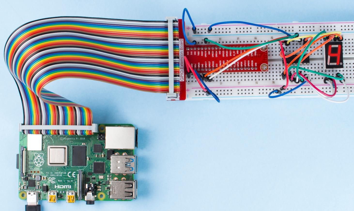
1.1.4 7-segment Display
Introduction
Let’s try to drive a 7-segment display to show a figure from 0 to 9 and A to F.
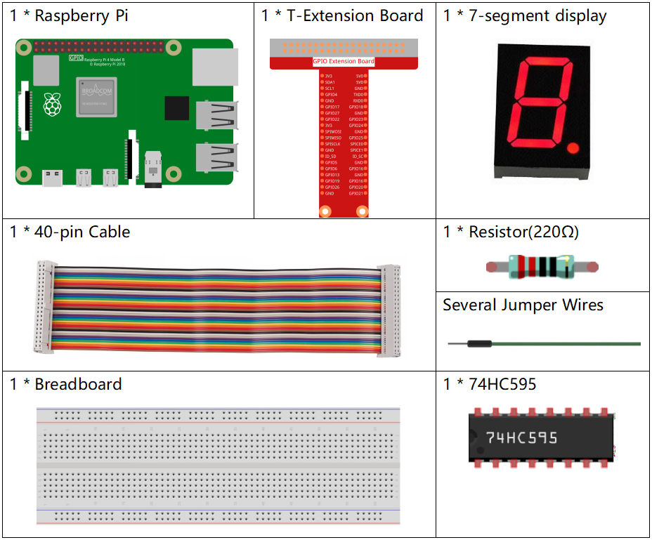
Required Components
In this project, we need the following components.
It’s definitely convenient to buy a whole kit, here’s the link:
Name |
ITEMS IN THIS KIT |
LINK |
|---|---|---|
Raphael Kit |
337 |
You can also buy them separately from the links below.
COMPONENT INTRODUCTION |
PURCHASE LINK |
|---|---|
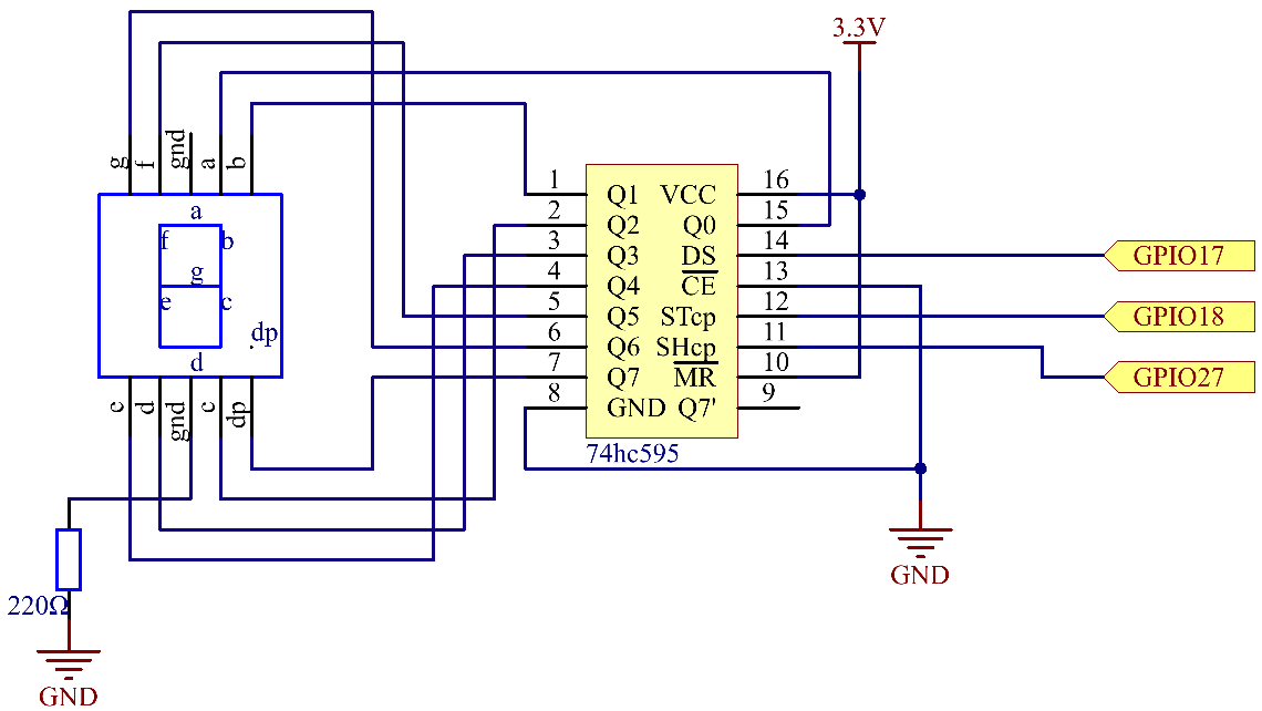
Schematic Diagram
Connect pin ST_CP of 74HC595 to Raspberry Pi GPIO18, SH_CP to GPIO27, DS to GPIO17, parallel output ports to 8 segments of the LED segment display. Input data in DS pin to shift register when SH_CP (the clock input of the shift register) is at the rising edge, and to the memory register when ST_CP (the clock input of the memory) is at the rising edge. Then you can control the states of SH_CP and ST_CP via the Raspberry Pi GPIOs to transform serial data input into parallel data output so as to save Raspberry Pi GPIOs and drive the display.
T-Board Name |
physical |
wiringPi |
BCM |
GPIO17 |
Pin 11 |
0 |
17 |
GPIO18 |
Pin 12 |
1 |
18 |
GPIO27 |
Pin 13 |
2 |
27 |
Experimental Procedures
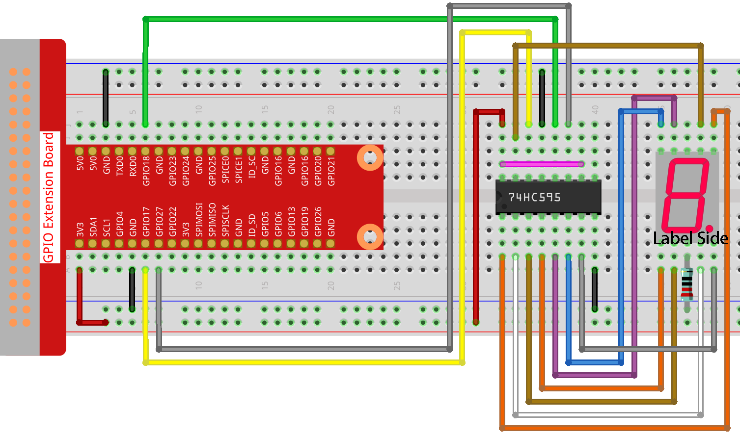
Step 1: Build the circuit.
Step 2: Get into the folder of the code.
cd ~/raphael-kit/c/1.1.4/
Step 3: Compile.
gcc 1.1.4_7-Segment.c -lwiringPi
Step 4: Run the executable file above.
sudo ./a.out
After the code runs, you’ll see the 7-segment display display 0-9, A-F.
Note
If it does not work after running, or there is an error prompt: "wiringPi.h: No such file or directory", please refer to Install and Check the WiringPi.
Code
#include <wiringPi.h>
#include <stdio.h>
#define   SDI   0   //serial data input
#define   RCLK  1   //memory clock input(STCP)
#define   SRCLK 2   //shift register clock input(SHCP)
unsigned char SegCode[16] = {0x3f,0x06,0x5b,0x4f,0x66,0x6d,0x7d,0x07,0x7f,0x6f,0x77,0x7c,0x39,0x5e,0x79,0x71};

void init(void){
    pinMode(SDI, OUTPUT);
    pinMode(RCLK, OUTPUT);
    pinMode(SRCLK, OUTPUT);
    digitalWrite(SDI, 0);
    digitalWrite(RCLK, 0);
    digitalWrite(SRCLK, 0);
}

void hc595_shift(unsigned char dat){
    int i;
    for(i=0;i<8;i++){
        digitalWrite(SDI, 0x80 & (dat << i));
        digitalWrite(SRCLK, 1);
        delay(1);
        digitalWrite(SRCLK, 0);
    }
        digitalWrite(RCLK, 1);
        delay(1);
        digitalWrite(RCLK, 0);
}

int main(void){
    int i;
    if(wiringPiSetup() == -1){ //when initialize wiring failed, print messageto screen
        printf("setup wiringPi failed !");
        return 1;
    }
    init();
    while(1){
        for(i=0;i<16;i++){
            printf("Print %1X on Segment\n", i); // %X means hex output
            hc595_shift(SegCode[i]);
            delay(500);
        }
    }
    return 0;
}
Code Explanation
unsigned char SegCode[16] = {0x3f,0x06,0x5b,0x4f,0x66,0x6d,0x7d,0x07,0x7f,0x6f,0x77,0x7c,0x39,0x5e,0x79,0x71};
A segment code array from 0 to F in Hexadecimal (Common cathode).
void init(void){
    pinMode(SDI, OUTPUT);
    pinMode(RCLK, OUTPUT);
    pinMode(SRCLK, OUTPUT);
    digitalWrite(SDI, 0);
    digitalWrite(RCLK, 0);
    digitalWrite(SRCLK, 0);
}
Set ds, st_cp, sh_cp three pins to OUTPUT, and the initial state as 0.
void hc595_shift(unsigned char dat){}
To assign 8 bit value to 74HC595’s shift register.
digitalWrite(SDI, 0x80 & (dat << i));
Assign the dat data to SDI(DS) by bits. Here we assume dat=0x3f(0011 1111, when i=2, 0x3f will shift left(<<) 2 bits. 1111 1100 (0x3f << 2) & 1000 0000 (0x80) = 1000 0000, is true.
digitalWrite(SRCLK, 1);
SRCLK’s initial value was set to 0, and here it’s set to 1, which is to generate a rising edge pulse, then shift the DS date to shift register.
digitalWrite(RCLK, 1);
RCLK’s initial value was set to 0, and here it’s set to 1, which is to generate a rising edge, then shift data from shift register to storage register.
while(1){
        for(i=0;i<16;i++){
            printf("Print %1X on Segment\n", i); // %X means hex output
            hc595_shift(SegCode[i]);
            delay(500);
        }
    }
In this for loop, we use %1X to output i as a hexadecimal number. Apply i to find the corresponding segment code in the SegCode[] array, and employ hc595_shift() to pass the SegCode into 74HC595’s shift register.
Note
The hexadecimal format of number 0~15 are (0, 1, 2, 3, 4, 5, 6, 7, 8, 9, A, B, C, D, E, F)
Phenomenon Picture