Note
Hello, welcome to the SunFounder Raspberry Pi & Arduino & ESP32 Enthusiasts Community on Facebook! Dive deeper into Raspberry Pi, Arduino, and ESP32 with fellow enthusiasts.
Why Join?
Expert Support: Solve post-sale issues and technical challenges with help from our community and team.
Learn & Share: Exchange tips and tutorials to enhance your skills.
Exclusive Previews: Get early access to new product announcements and sneak peeks.
Special Discounts: Enjoy exclusive discounts on our newest products.
Festive Promotions and Giveaways: Take part in giveaways and holiday promotions.
👉 Ready to explore and create with us? Click [here] and join today!
1.1.2 RGB LED
Introduction
In this project, we will control an RGB LED to flash various colors.
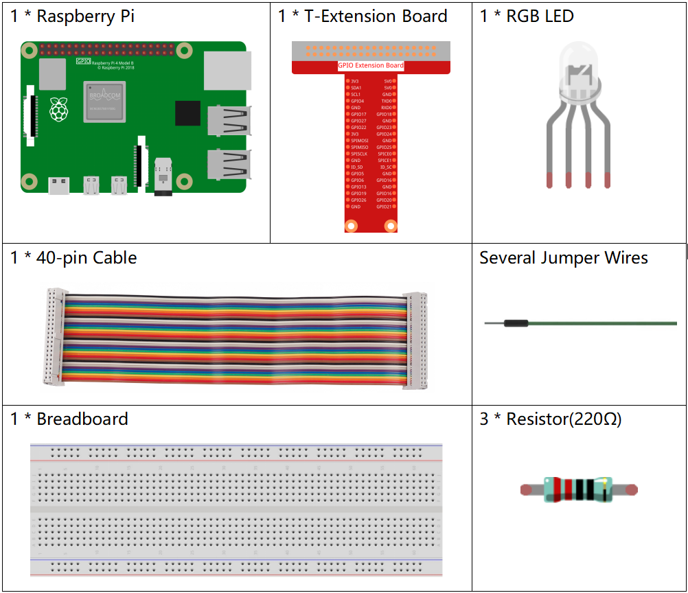
Required Components
In this project, we need the following components.
It’s definitely convenient to buy a whole kit, here’s the link:
Name |
ITEMS IN THIS KIT |
LINK |
|---|---|---|
Raphael Kit |
337 |
You can also buy them separately from the links below.
COMPONENT INTRODUCTION |
PURCHASE LINK |
|---|---|
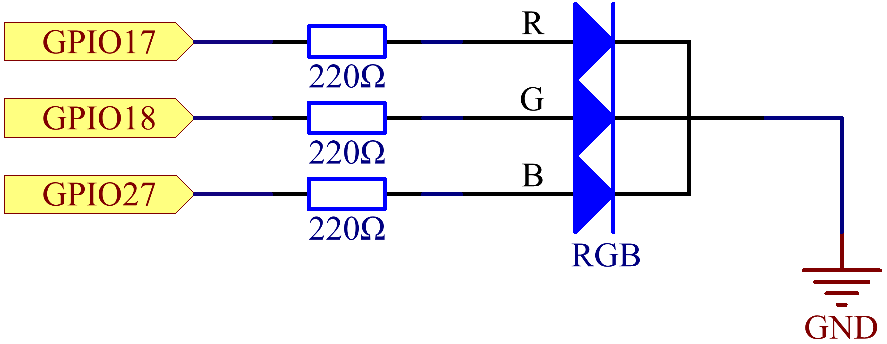
Schematic Diagram
After connecting the pins of R, G, and B to a current limiting resistor, connect them to the GPIO17, GPIO18, and GPIO27 respectively. The longest pin (GND) of the LED connects to the GND of the Raspberry Pi. When the three pins are given different PWM values, the RGB LED will display different colors.
T-Board Name |
physical |
wiringPi |
BCM |
GPIO17 |
Pin 11 |
0 |
17 |
GPIO18 |
Pin 12 |
1 |
18 |
GPIO27 |
Pin 13 |
2 |
27 |
Experimental Procedures
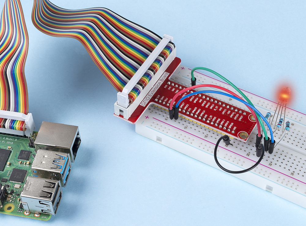
Step 1: Build the circuit.

Step 2: Go to the folder of the code.
cd ~/raphael-kit/c/1.1.2/
Step 3: Compile the code.
gcc 1.1.2_rgbLed.c -lwiringPi
Note
When the instruction gcc is executed, if -o is not called, then the executable file is named a.out.
Step 4: Run the executable file.
sudo ./a.out
After the code runs, you will see that RGB displays red, green, blue, yellow, pink, and cyan.
Note
If it does not work after running, or there is an error prompt: "wiringPi.h: No such file or directory", please refer to Install and Check the WiringPi.
Code
#include <wiringPi.h>
#include <softPwm.h>
#include <stdio.h>
#define uchar unsigned char
#define LedPinRed    0
#define LedPinGreen  1
#define LedPinBlue   2

void ledInit(void){
    softPwmCreate(LedPinRed,  0, 100);
    softPwmCreate(LedPinGreen,0, 100);
    softPwmCreate(LedPinBlue, 0, 100);
}

void ledColorSet(uchar r_val, uchar g_val, uchar b_val){
    softPwmWrite(LedPinRed,   r_val);
    softPwmWrite(LedPinGreen, g_val);
    softPwmWrite(LedPinBlue,  b_val);
}

int main(void){

    if(wiringPiSetup() == -1){ //when initialize wiring failed, printf messageto screen
        printf("setup wiringPi failed !");
        return 1;
    }

    ledInit();
    while(1){
        printf("Red\n");
        ledColorSet(0xff,0x00,0x00);   //red
        delay(500);
        printf("Green\n");
        ledColorSet(0x00,0xff,0x00);   //green
        delay(500);
        printf("Blue\n");
        ledColorSet(0x00,0x00,0xff);   //blue
        delay(500);
        printf("Yellow\n");
        ledColorSet(0xff,0xff,0x00);   //yellow
        delay(500);
        printf("Purple\n");
        ledColorSet(0xff,0x00,0xff);   //purple
        delay(500);
        printf("Cyan\n");
        ledColorSet(0xc0,0xff,0x3e);   //cyan
        delay(500);
    }
    return 0;
}
Code Explanation
#include <softPwm.h>
Library used for realizing the pwm function of the software.
void ledInit(void){
    softPwmCreate(LedPinRed,  0, 100);
    softPwmCreate(LedPinGreen,0, 100);
    softPwmCreate(LedPinBlue, 0, 100);
}
The function is to use software to create a PWM pin, set its period between 0x100us-100x100us.
The prototype of the function softPwmCreate(LedPinRed, 0, 100) is as follows:
int softPwmCreate(int pin,int initialValue,int pwmRange);
Parameter pin: Any GPIO pin of Raspberry Pi can be set as a PWM pin.
Parameter initialValue: The initial pulse width is that initialValue times100us.
Parameter pwmRange: the period of PWM is that pwmRange times100us.
void ledColorSet(uchar r_val, uchar g_val, uchar b_val){
    softPwmWrite(LedPinRed,   r_val);
    softPwmWrite(LedPinGreen, g_val);
    softPwmWrite(LedPinBlue,  b_val);
}
This function is to set the colors of the LED. Using RGB, the formal parameter r_val represents the luminance of the red one, g_val of the green one, b_val of the blue one.
The prototype of the function softPwmWrite(LedPinBlue, b_val) is as follows:
void softPwmWrite (int pin, int value) ;
Parameter pin: Any GPIO pin of Raspberry Pi can be set as a PWM pin.
Parameter Value: The pulse width of PWM is value times 100us. Note that value can only be less than pwmRange defined previously, if it is larger than pwmRange, the value will be given a fixed value, pwmRange.
ledColorSet(0xff,0x00,0x00);
Call the function defined before. Write 0xff into LedPinRed and 0x00 into LedPinGreen and LedPinBlue. Only the Red LED lights up after running this code. If you want to light up LEDs in other colors, just modify the parameters.
Phenomenon Picture