Lesson 12: Driving the Rover with the App
In our last adventure, we mastered the art of using the SunFounder Controller to not only explore the world through the rover’s eyes but also to adjust its gaze by controlling the tilt mechanism. It was like giving our Mars rover a sense of sight!
Now, imagine if you could steer this Martian explorer as well, directing its path at your whim. In this lesson, that’s exactly what we’re going to do! We’re going to take our understanding of the SunFounder Controller to the next level and learn to maneuver our rover, giving us the thrilling experience of being a Mars rover driver!
With our vivid and lively STEAM course, children will not just learn; they’ll experience the excitement and wonder of space exploration! Strap in and get ready for an exciting journey!
Learning Goals
Gain a deeper understanding of the SunFounder Controller.
Learn how to drive the Mars rover using the mobile app.
Materials needed
Mars Rover model (equipped with all components, except for solar panel and bottom plate)
Arduino IDE
Computer
Tablet or smartphone with SunFounder Controller app installed
Course Steps
Step 1: Dive Deeper into the SunFounder Controller
In our previous lesson, we got our first taste of the SunFounder Controller, its basic operations and uses. But surely, you’re left with some burning questions, right? Time to quench that curiosity and delve deeper into this tech marvel.
On creating a new controller, you’ll be met with a screen that might look like an enigma at first.
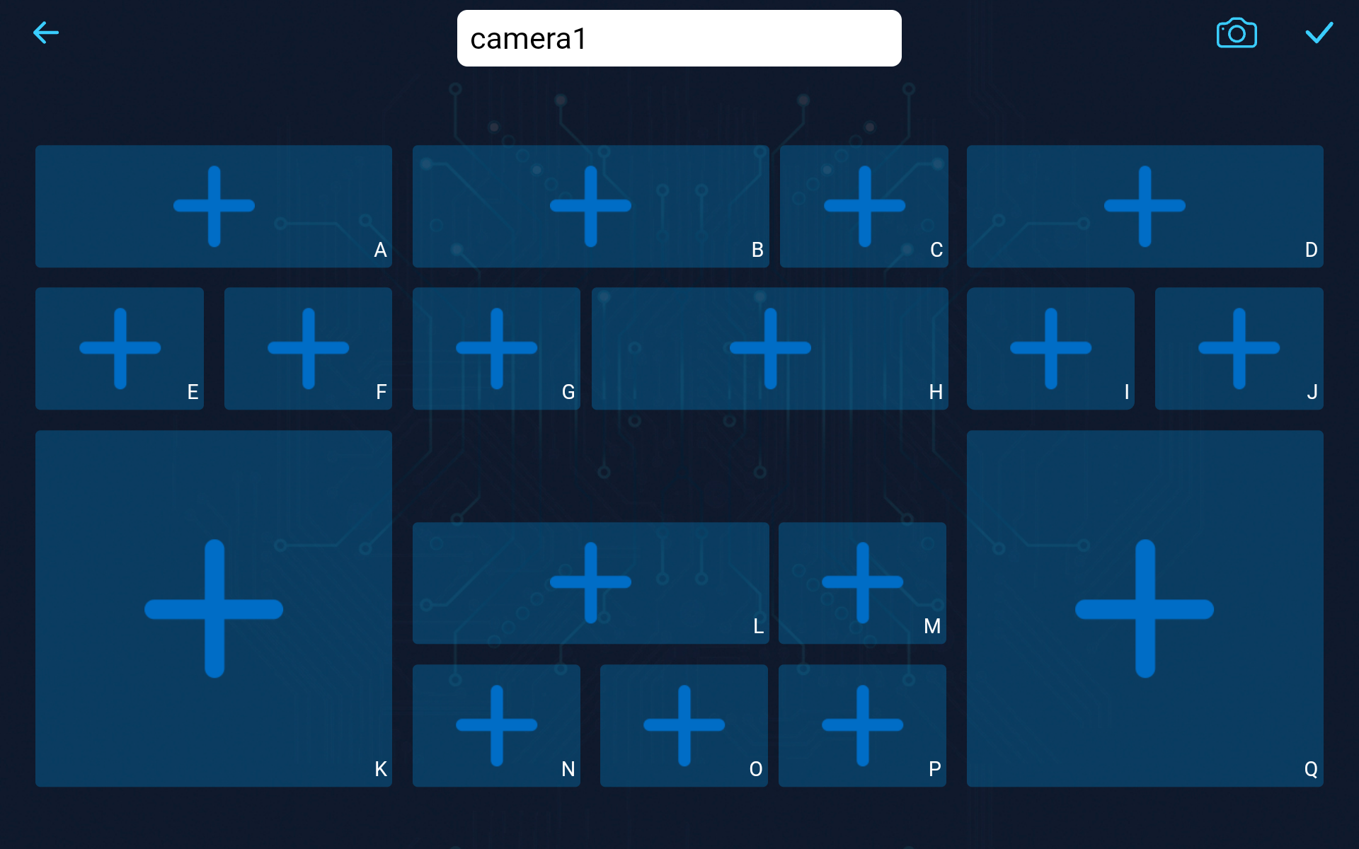
You’ll see a kaleidoscope of shapes: long rectangles, short rectangles, and large squares, each uniquely tagged with identifiers from A to Q.
Ever wondered why such diversity? What do the identifiers A to Q imply?
Let’s embark on this exploratory journey!
Deciphering the Shapes
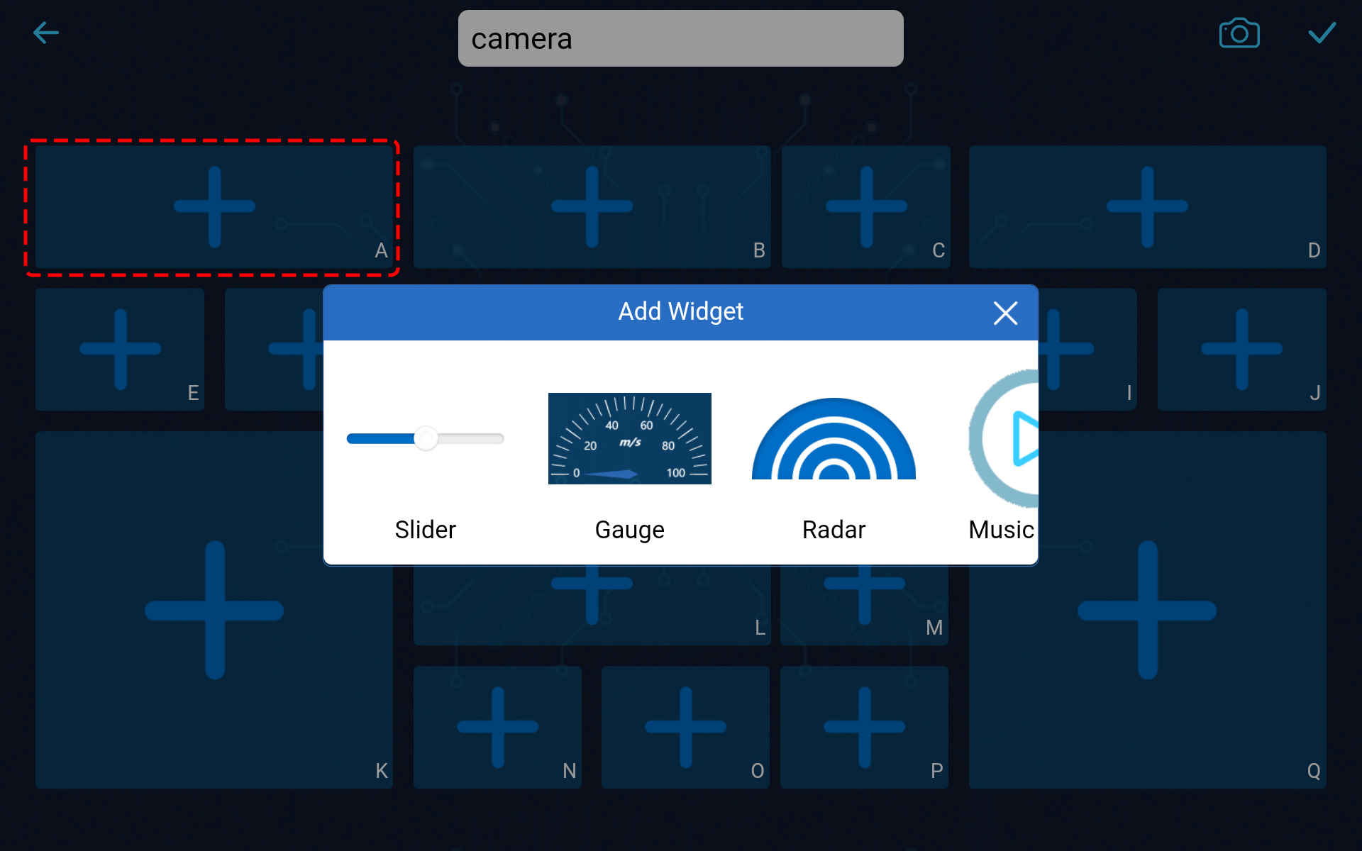
For instance, tap on a long rectangular area. Like opening a treasure chest, you’ll unveil several widgets. Remember the Slider from our previous class? Swiping it left or right controlled the Mars rover’s camera tilt. Then there’s the Gauge, can be used as your rover’s personal speedometer. And a plethora of other widgets!
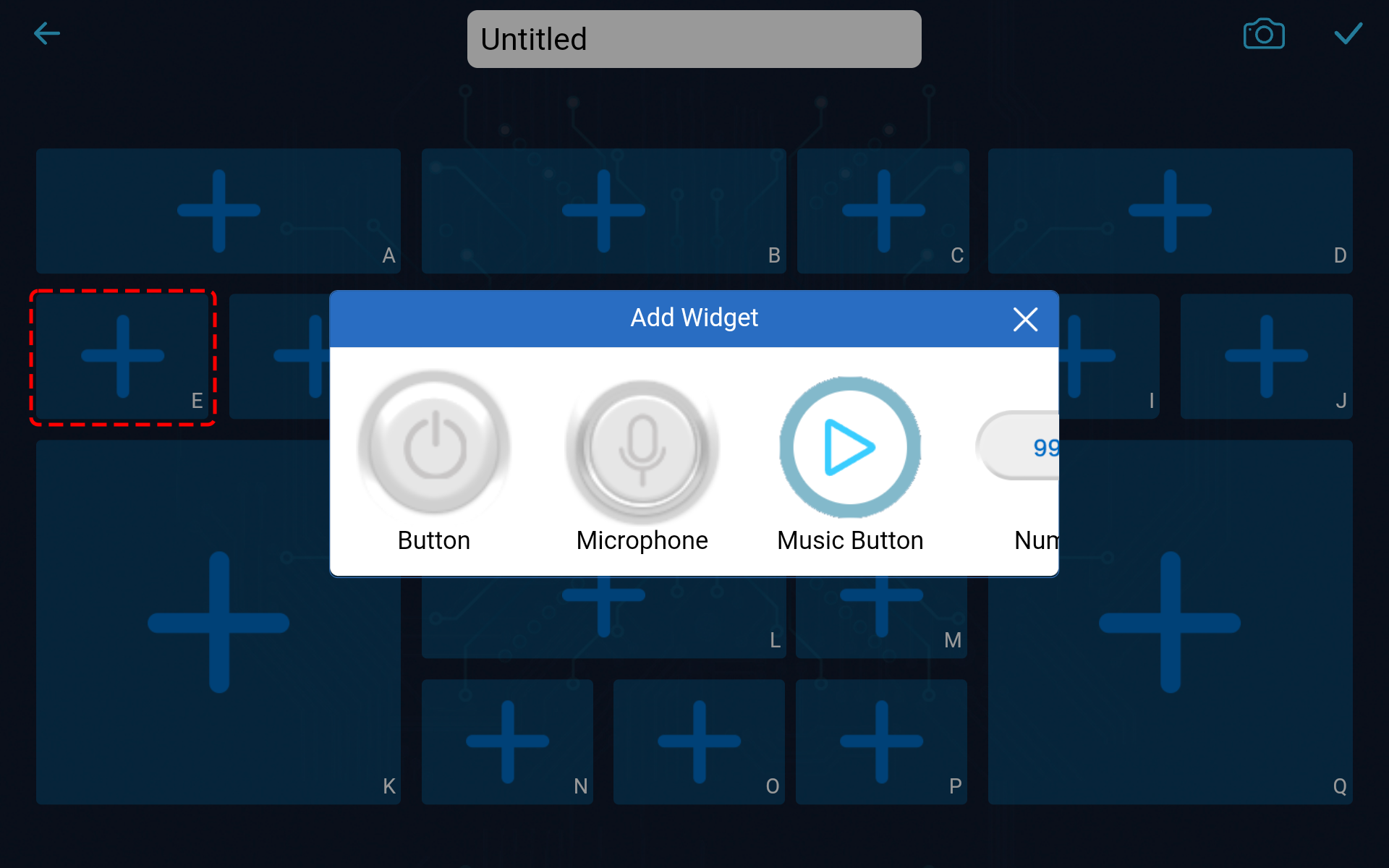
Tap on the shorter rectangle, and it reveals a different set of widgets. The Button widget, like a binary switch, issues singular commands, while the Microphone widget can listens to your voice commands to control the rover, among other widgets.
What about the square block, you ask? It houses the Joystick widget, the D-pad widget, and the Throttle widget. And yes, there’s more!
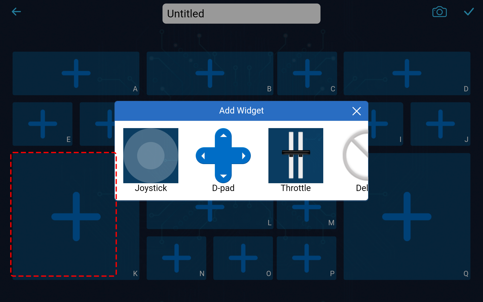
At this point, don’t fret about each widget’s function or usage. Familiarize yourself with what widgets each shape houses.
Harnessing the Widgets
Through the content above, we know that there are many different widgets. So what can these widgets be used for?
We categorize these widgets into two types: control widgets and show widgets.
Control widgets primarily let you manipulate the app, and then the Mars rover receives these control commands and performs corresponding actions.
Show widgets allow you to use them to show some values in the app, such as sensor values, etc.
For a detailed description of these widgets, please refer to: Widgets List.
Also, for the functions, parameters, etc. related to these widgets, please refer to: Widgets Usage.
The Role of Identifiers
Every shape carries an identifier on the bottom right corner. Why, you ask? Let’s understand this with an example.
In our last class, we added a Slider widget in the D region. The code to get its value looked something like this:
int16_t sliderD = aiCam.getSlider(REGION_D);
What if we added a Slider widget in the B region? How would the code change? As simple as replacing
REGION_DwithREGION_B.int16_t sliderD = aiCam.getSlider(REGION_B);
Easy, right? These identifiers help discern which widget you’ve added in which area.
Note
Detailed instructions on creating and adding widgets, and connecting and operating the SunFounder Controller, are available in
Step 3ofLesson 11.For more in-depth operations, please visit Page Introduction.
Step 2: Control the Mars Rover with Dual Throttles
Now that we’ve delved into the ins and outs of the SunFounder Controller widgets, let’s elevate our game by incorporating two Throttle widgets to commandeer the movement of the Mars Rover.
Place a Throttle widget each in the K and Q regions. You will need to hit the
 button at the top right to switch to editing mode, and once you’re done setting things up, click
  to store your changes.
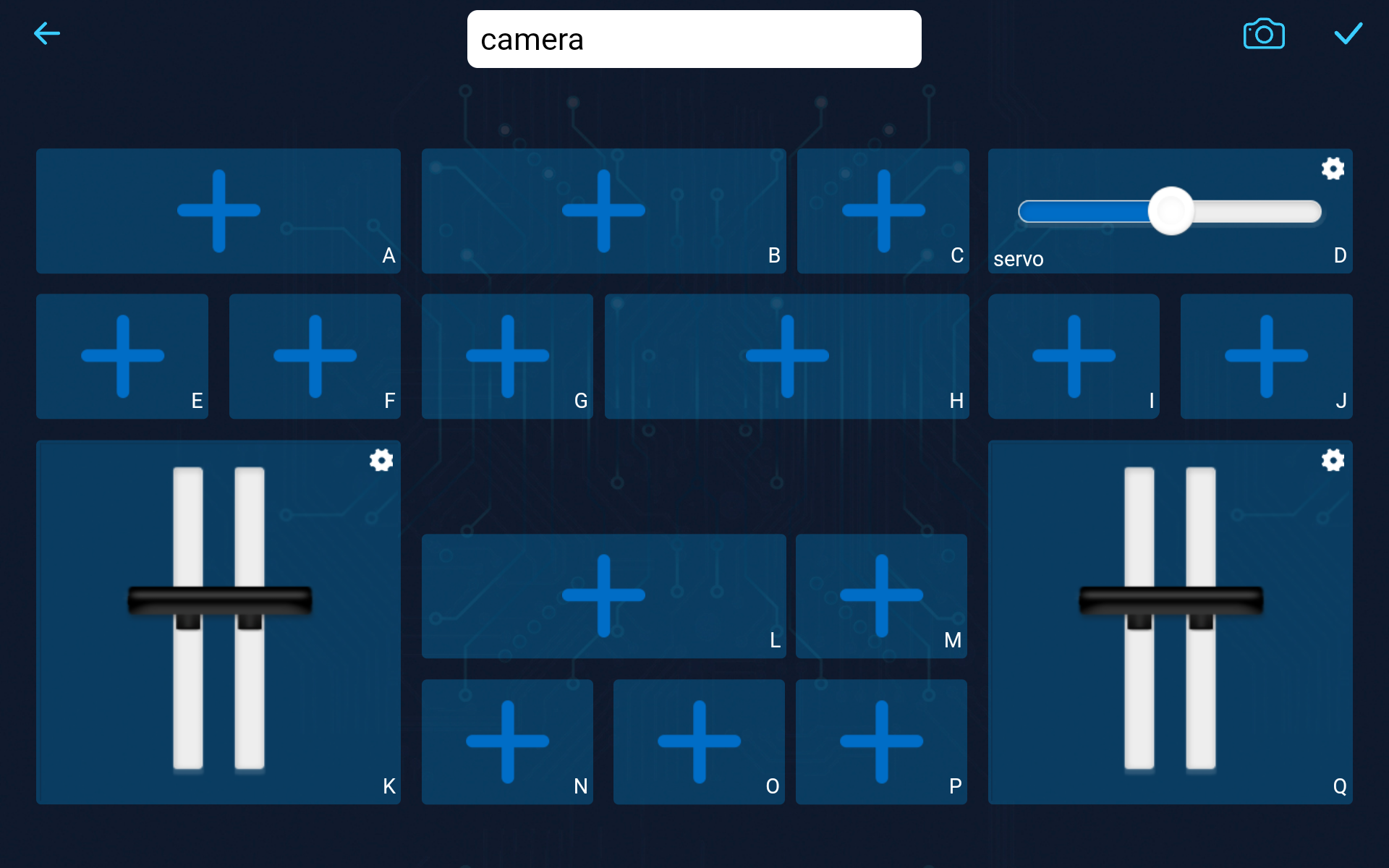
Since we plan to utilize two Throttle widgets to govern the Rover’s mobility, let’s tweak the function that dictates the rover’s movements accordingly:
// Function to set the power of the motors
void carSetMotors(int8_t power_L, int8_t power_R) {
    // Set power for the left motor
    if (power_L >= 0) {
        SoftPWMSet(in1, map(power_L, 0, 100, 0, 255));
        SoftPWMSet(in2, 0);
    } else {
        SoftPWMSet(in1, 0);
        SoftPWMSet(in2, map(power_L, 0, -100, 0, 255));
    }

    // Set power for the right motor
    if (power_R >= 0) {
        SoftPWMSet(in3, 0);
        SoftPWMSet(in4, map(power_R, 0, 100, 0, 255));
    } else {
        SoftPWMSet(in3, map(power_R, 0, -100, 0, 255));
        SoftPWMSet(in4, 0);
    }
}
Sure, let’s break down the
carSetMotors()function. This function accepts two arguments,power_Landpower_R, which are likely the power settings for the left and right motors respectively. The values of these arguments are presumably from -100 to 100, where negative values indicate reverse motion, 0 indicates stop, and positive values indicate forward motion.Set power for the left motor:
If
power_Lis greater than or equal to 0, the left motor is set to move forward.SoftPWMSet(in1, map(power_L, 0, 100, 0, 255))uses the Arduinomapfunction to map the input range (0 to 100) to the output range (0 to 255) - this is because PWM values in Arduino are between 0 (0% duty cycle) and 255 (100% duty cycle). This mapped value is then passed to theSoftPWMSetfunction along within1.If
power_Lis less than 0, the left motor is set to move in reverse and the input range for themapfunction is now 0 to -100.
Set power for the right motor:
This follows the same logic as setting the power for the left motor, but uses
in3andin4instead, and the input power values arepower_Rinstead ofpower_L.
Overall, this function takes two motor power values, converts them into the appropriate PWM values, and sets the PWM values on the correct motor control pins to achieve the desired motion.
Within the
onReceive()function, retrieve the values from the two Throttle widgets and employ them as the power for the left and right motors of the Mars Rover.void onReceive() { // Get the value of the slider in region D int16_t sliderD = aiCam.getSlider(REGION_D); // Move the servo to the angle indicated by the slider myServo.write(int(sliderD)); // Get the throttle values for the left and right int throttle_L = aiCam.getThrottle(REGION_K); int throttle_R = aiCam.getThrottle(REGION_Q); // Set the power for the motors carSetMotors(throttle_L, throttle_R); }
Here is the complete code:
Each time you rerun the code, you need to repeat the following four steps:
Prior to uploading the code, ensure the switch is turned to the right.
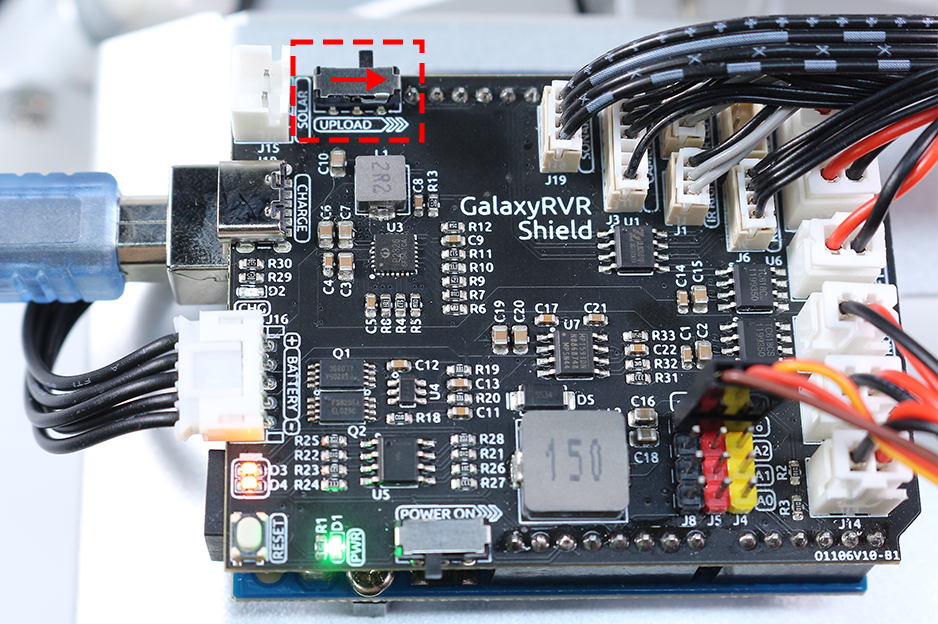
Once the code has been successfully uploaded, switch to the left to initiate the ESP32 CAM.
Connect to the
GalaxyRVRNetwork.Connect and run the controller.
Now, with a simple glide of the thumb on your Throttle widgets, you’ll witness the Mars Rover in action, powering and pivoting with a renewed spirit. Let the exploration commence!
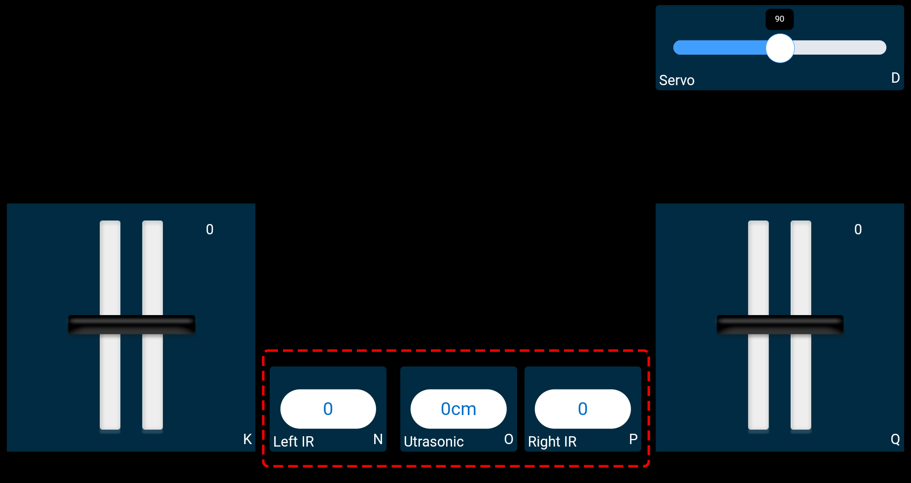
Step 3: Visualizing Sensor Readings
In our journey with the SunFounder Controller, we have been actively interacting with our Mars rover through control widgets, including sliders for adjusting the tilt and throttles for dictating the rover’s movement. But what about harnessing the power of display widgets to paint a vivid picture of our rover’s surroundings?
Let’s see how we can bring this to life by visualizing the values from the left and right infrared (IR) avoidance modules and the distance captured by the ultrasonic module. This real-time data will provide us with a clear snapshot of the rover’s operating environment.
Here’s how we can achieve this:
Get started by adding three Number widgets to your SunFounder Controller. Don’t forget, you can personalize their names and units using the settings button.
Next, let’s delve into the code. Start by bringing over the IR avoidance modules and ultrasonic module code snippets from our previous lessons.
...
// Define the pin for the ultrasonic module
#define ULTRASONIC_PIN 10

// Define the pins for the IR modules
#define IR_RIGHT 7
#define IR_LEFT 8

void setup() {
    ...

    // Set the IR module pins as inputs
    pinMode(IR_RIGHT, INPUT);
    pinMode(IR_LEFT, INPUT);
}


float readSensorData() {
    // A 4ms delay is required, otherwise the reading may be 0
    delay(4);

    //Set to OUTPUT to send signal
    pinMode(ULTRASONIC_PIN, OUTPUT);

    ...
}
In the
onReceive()function, extract the values from the avoidance modules and the ultrasonic sensor. Subsequently, update these values in thesendDoc[]dictionary. TheN,P, andOkeys correspond to the region codes of the three Number widgets you’ve added.// Function to execute when data is received from the Controller void onReceive() { ... // Read values from IR sensors int leftValue = digitalRead(IR_LEFT); int rightValue = digitalRead(IR_RIGHT); aiCam.sendDoc["N"] = leftValue; aiCam.sendDoc["P"] = rightValue; // ultrasonic float distance = readSensorData(); aiCam.sendDoc["O"] = distance; }
Here is the complete code:
Once the code has been successfully uploaded, get your SunFounder Controller up and running. You’ll be greeted with the real-time values of the avoidance modules and the distance detected by the ultrasonic sensor, painting a clear picture of the rover’s immediate environment.
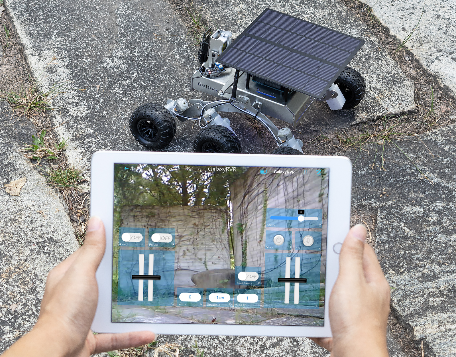
With this step behind you, you’ve successfully navigated the world of show widgets. Feel free to experiment with different widgets to display the information that you find interesting. Happy exploring!
Step 4: Reflection and Conclusion
In this lesson, we’ve forged a deeper understanding of the SunFounder Controller, grasping how we can utilize its widgets to not only steer our Mars rover but also monitor its environmental data in real time.
Now, here’s a challenge for you:
How about adding some Switch widgets to your SunFounder Controller? With these switches activated, the Mars rover could switch between avoidance and follow modes. Or, why not use the switches to control the light strip – switching it on or off, or even changing its color?
Do you have the confidence to take this on?
We’re looking forward to seeing you conquer this challenge!