Lesson 11: Exploring the Mars Rover Visual System - Camera and Real-time Control
Welcome back, young explorers! In the last lesson, we equipped our Mars Rover with the ability to “nod” using a tilt mechanism. Now, it’s time to give our Rover “eyes” - the camera!
In this thrilling journey, we’ll dive into the setup of the Rover’s camera system. You’ll learn how to relay the visuals captured by the Rover’s camera to a web page, so you can see exactly what the Rover sees, in real time. Imagine the excitement of experiencing the Martian landscape from the Rover’s perspective!
The excitement continues as we also introduce the SunFounder Controller app. This application allows us to get a live feed of the Rover’s view as it navigates around, and we can control the tilt mechanism directly from our smartphones or tablets. It’s like having a remote control with a built-in screen!
This offers an even more interactive and engaging experience with our Rover. Stay tuned for more adventures!
Learning Goals
Understand how to establish a WiFi connection with the ESP32 CAM.
Learn how to see exactly what the Rover sees, in real time.
Learn how to use the SunFounder Controller app to create a virtual remote and control the Mars Rover.
Materials needed
Mars Rover model (equipped with all components)
Arduino IDE
Computer
Tablet or smartphone with SunFounder Controller app installed
Course Steps
Step 1: Introduction to ESP32 CAM
In our previous adventure, we have equipped our Mars Rover with a pair of “eyes” by integrating the ESP32 CAM. Today, we’re going to learn more about it and actually make it “see”.
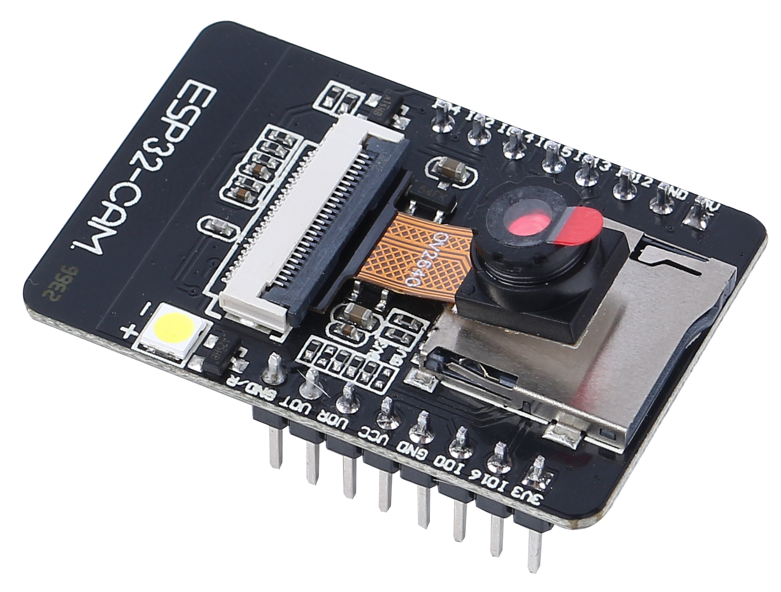
The ESP32 CAM, acting like the eyes of our Rover, is a small yet powerful module. Not only does it integrate Wi-Fi and Bluetooth functionalities, it also comes with a compact camera. This camera helps our Rover capture images of its surroundings.
Just like we use our eyes to observe our environment, the ESP32 CAM can “see” what lies ahead for the Rover, then send these visual data to our smartphone or computer. This allows us to see everything the Rover sees in real-time!
It’s as if we’re piloting the Rover directly, observing not just the Rover itself, but also the world it explores! Incredible, isn’t it? So, let’s dive deeper into it…
Step 2: Programming the Rover’s Camera and Viewing the Feed
After fitting the ESP32-CAM to our Rover, we now need to breathe life into it. To do so, we will use the Arduino IDE to write a program that will control the camera, allow it to connect to WiFi, and stream the visuals it captures.
Here’s how we can do it:
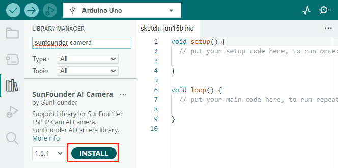
Install the
SunFounder AI Cameralibrary.Open the Arduino IDE’s Library Manager, search for “SunFounder Camera”, and click INSTALL.
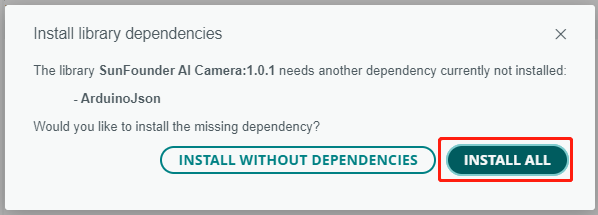
A pop-up window will appear for the installation of library dependencies. Click INSTALL ALL and wait for the process to complete.
In the Arduino IDE, input the following code.
Regarding the variables
NAME,TYPE, andPORTin the code, let’s not delve into them at this point. They will come into play in our next step. Just keep in mind that these variables will be important in our upcoming journey to establish a real-time video feed from our Mars Rover.Notice we have two connection modes in the code - AP mode and STA mode. You can decide which one to use based on your specific needs.
AP Mode: In this mode, the Rover creates a hotspot (named as
GalaxyRVRin our code). This allows any device like a mobile phone, tablet, or laptop to connect to this network. This is especially useful when you want to control the Rover remotely under any circumstances. However, note that this would make your device temporarily unable to connect to the Internet.// AP Mode #define WIFI_MODE WIFI_MODE_AP #define SSID “GalaxyRVR” #define PASSWORD “12345678”
STA Mode: In this mode, the Rover connects to your home WiFi network. Remember that your controlling device (like a mobile phone or tablet) should also be connected to the same WiFi network. This mode allows your device to keep its regular internet access while controlling the Rover, but limits the Rover’s operational range to your WiFi coverage area.
// STA Mode
#define WIFI_MODE WIFI_MODE_STA
#define SSID "YOUR SSID"
#define PASSWORD "YOUR PASSWORD"
Upload the code to our Rover and bring our ESP32 CAM to life!
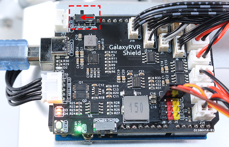
The ESP32-CAM and the Arduino board share the same RX (receive) and TX (transmit) pins. So, before uploading the code, you’ll need to first release the ESP32-CAM by slide this switch to right side to avoid any conflicts or potential issues.
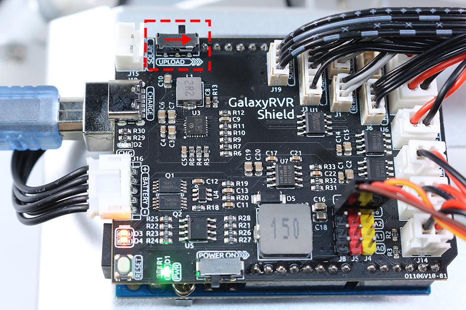
Once the code has been uploaded successfully, switch it back to the left side to start the ESP32 CAM.
Note
This step and the previous one are required every time you re-upload the code.
Open the Serial Monitor and set the baud rate to 115200. If no information appears, press the Reset button on the GalaxyRVR shield to run the code again. You should see an IP address in the serial monitor output. This is the address your Rover’s camera is broadcasting to.
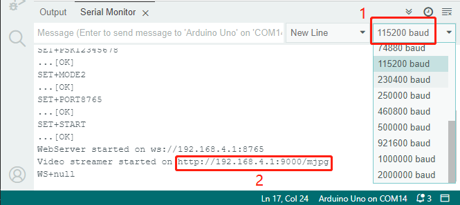
Now, it’s time to actually see what our Rover sees! Open up a web browser - we recommend Google Chrome - and enter the URL you see in the Serial Monitor, in the format
http://ip:9000/mjpg.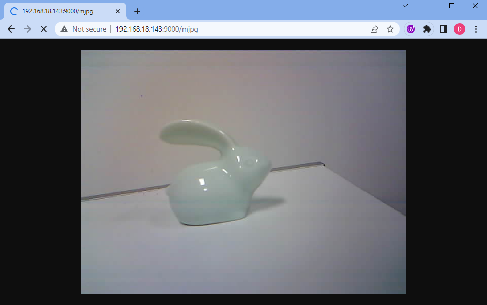
And voila! You should now be able to see the live feed from your Rover’s camera. Isn’t it amazing to think that you are viewing Mars (or maybe just your living room) from the Rover’s perspective? Just like a real Mars Rover scientist!
Remember, this is just the beginning. There is so much more to explore and learn. In our next step, we will explore how to control our Rover while viewing the live camera feed. Exciting, isn’t it? Onwards, explorers!
Step 3: Controlling and Viewing the Camera Feed Using the App
Ever wished you could view the Mars Rover’s visual feed right on your smartphone while also being able to control its tilt mechanism? Now you can! With the help of the SunFounder Controller app, you’ll be able to do exactly that. Follow the steps below:
Install from APP Store(iOS) or Google Play(Android).
Create a controller.
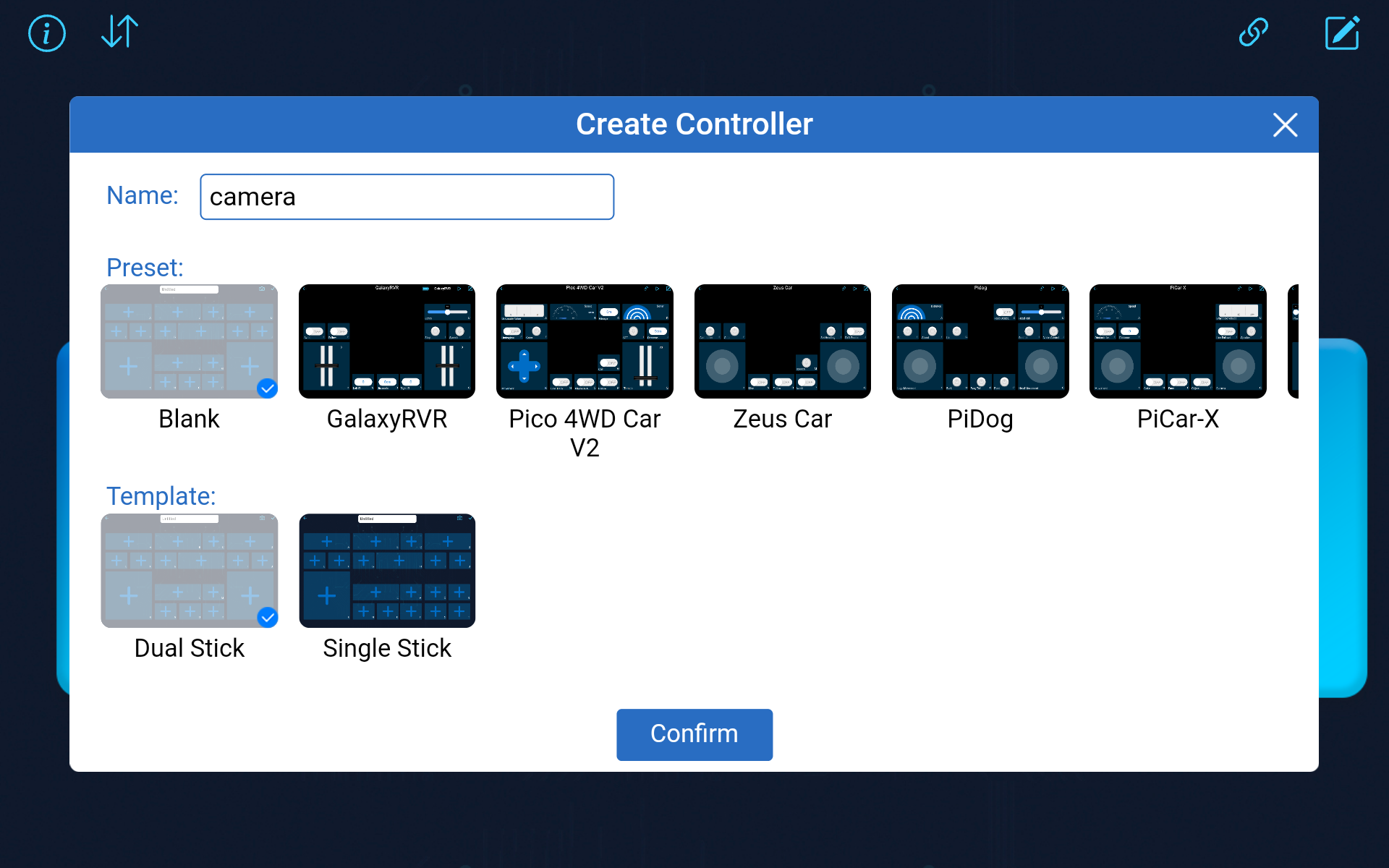
To add a controller on SunFounder Controller, click the + icon.
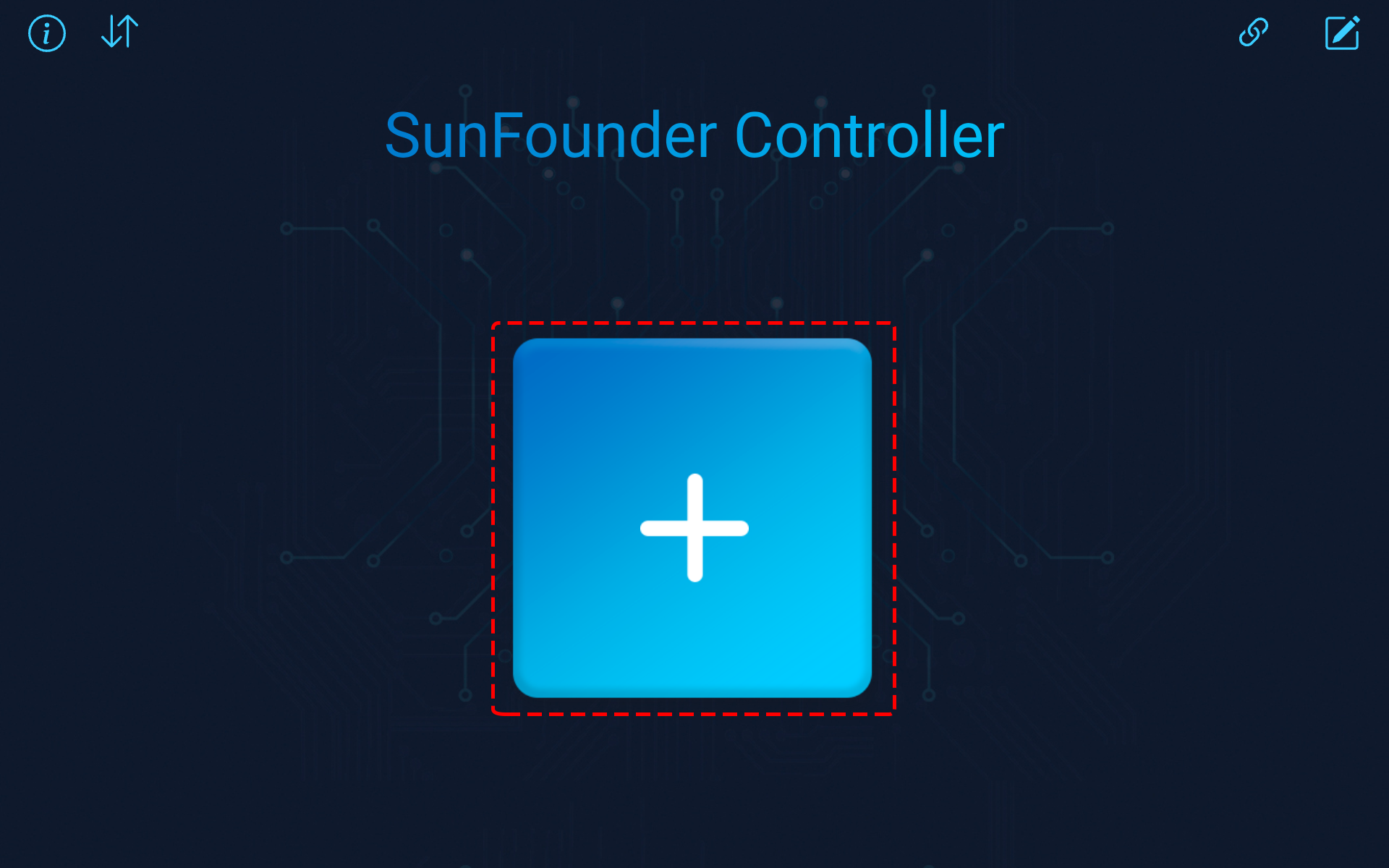
Choose the Blank preset, select either Dual or Single Stick according to your preference. Give your new controller a name and click Confirm.
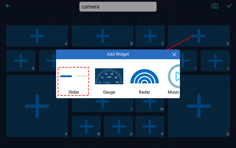
You are now inside the controller. Click the + icon in the D section, then select Slider from the popup menu.
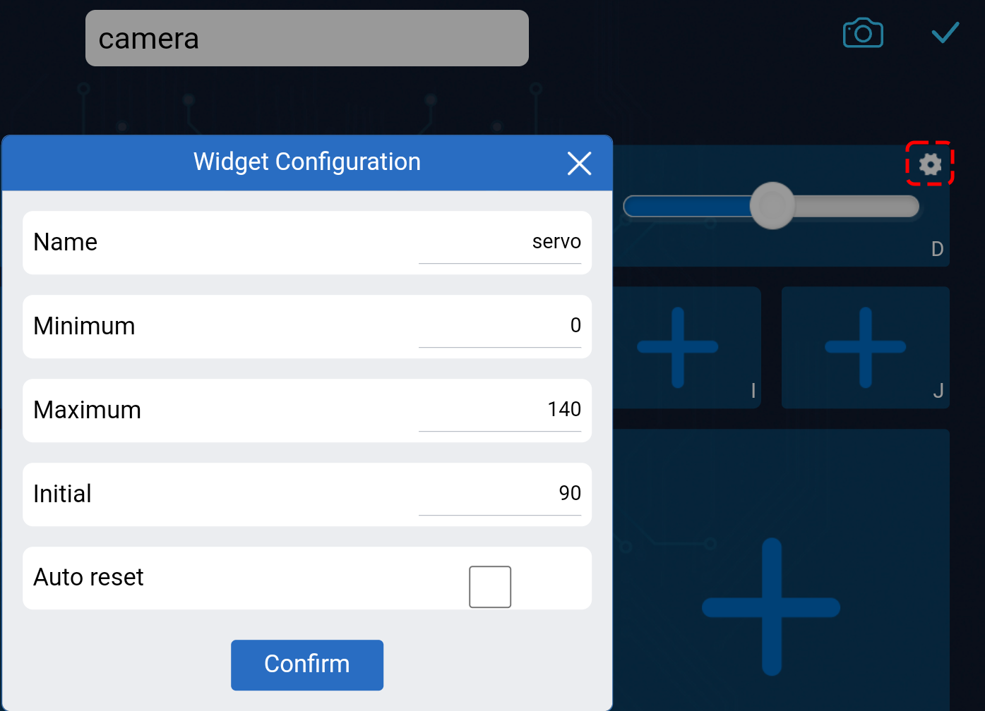
This Slider widget is designed to control the tilt mechanism. As we learned in the previous lesson, its range is from 0 to 140. Therefore, we will set these as the minimum and maximum values for our Slider widget.
Click the
 button in the upper right corner to save this controller.
Let’s write a code to capture the value of the slider:
Based on the previous code, let’s switch to AP mode, where you can set the SSID and PASSWORD to whatever you prefer.
// AP Mode
#define WIFI_MODE WIFI_MODE_AP
#define SSID "GalaxyRVR"
#define PASSWORD "12345678"
Next, we add an
onReceive()function to receive values from the SunFounder Controller and print these values in the Serial Monitor. We use thegetSlider()function to get the value of the slider widget. I added a slider widget in Region D, but if you added it in a different region, you need to changeREGION_Dto your region.void onReceive() { int16_t sliderD = aiCam.getSlider(REGION_D); Serial.print("Slider D: "); Serial.println(sliderD); } void setup() { ... // Set the function to execute when data is received aiCam.setOnReceived(onReceive); ... }
Here is the complete code:
Before uploading the code, make sure the switch is turned to the right.
After the code is successfully uploaded, move the switch to the left to start the ESP32 CAM.
When you see the following information in the Serial Monitor, you can move on to the next step.
...[OK]
SET+PORT8765
...[OK]
SET+START
...[OK]
WebServer started on ws://192.168.4.1:8765
Video streamer started on http://192.168.4.1:9000/mjpg
WS+null
Connect to the
GalaxyRVRNetwork.At this point, you should connect your mobile device to the local area network (LAN) provided by the GalaxyRVR. By doing this, both your mobile device and the Rover will be on the same network, enabling smooth communication between the applications on your mobile device and the Rover.
Find
GalaxyRVRon the list of available networks on your mobile device (tablet or smartphone), enter the password12345678, and connect to it.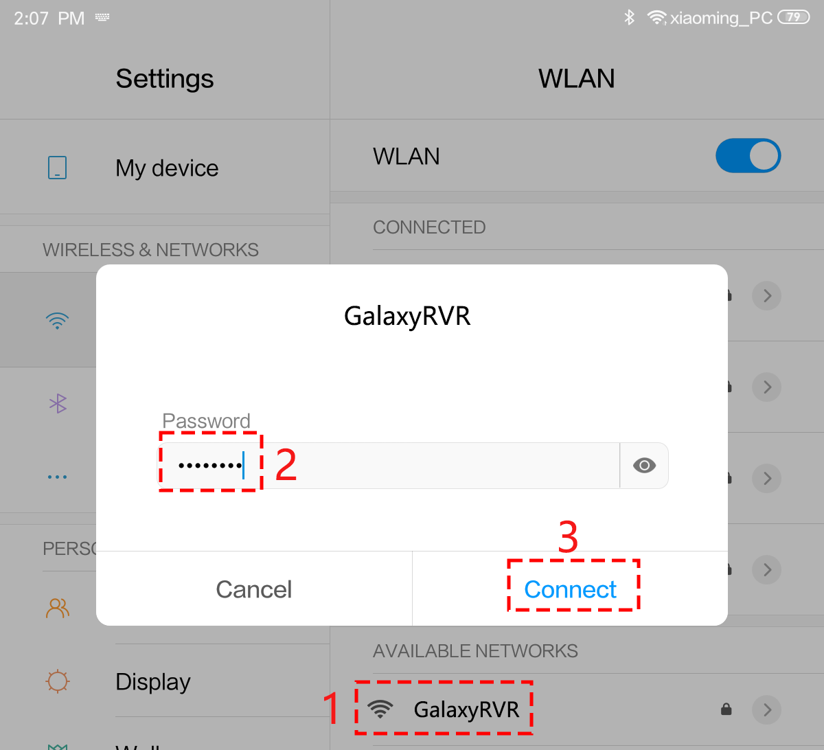
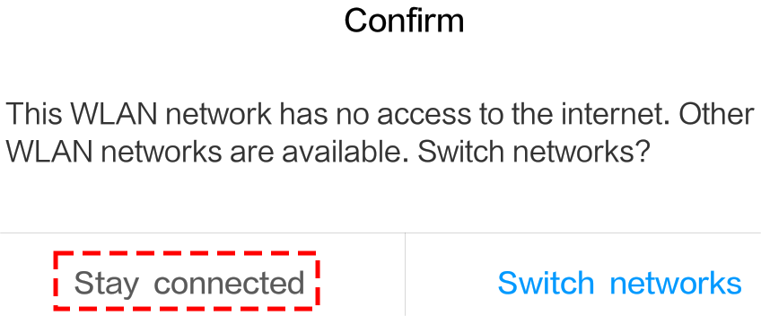
The default connection mode is AP mode. After you connect, there may be a prompt warning you that there is no Internet access on this WLAN network, please choose to continue the connection.
Connect and Activate the Controller.
Now, return to the controller you created earlier (in my case, it’s named “camera”). Use the
 button to link the SunFounder Controller to the Rover and establish a line of communication. After a brief wait,
 GalaxyRVR(IP)(the name you assigned in the code with#define NAME "GalaxyRVR") will appear. Click on it to establish a connection.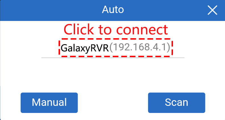
Note
Please verify that your Wi-Fi is connected to
GalaxyRVRif you don’t see the above message after some time.Once you see the “Connected Successfully” message, press the
 button. This will bring up the camera’s live footage on the app.
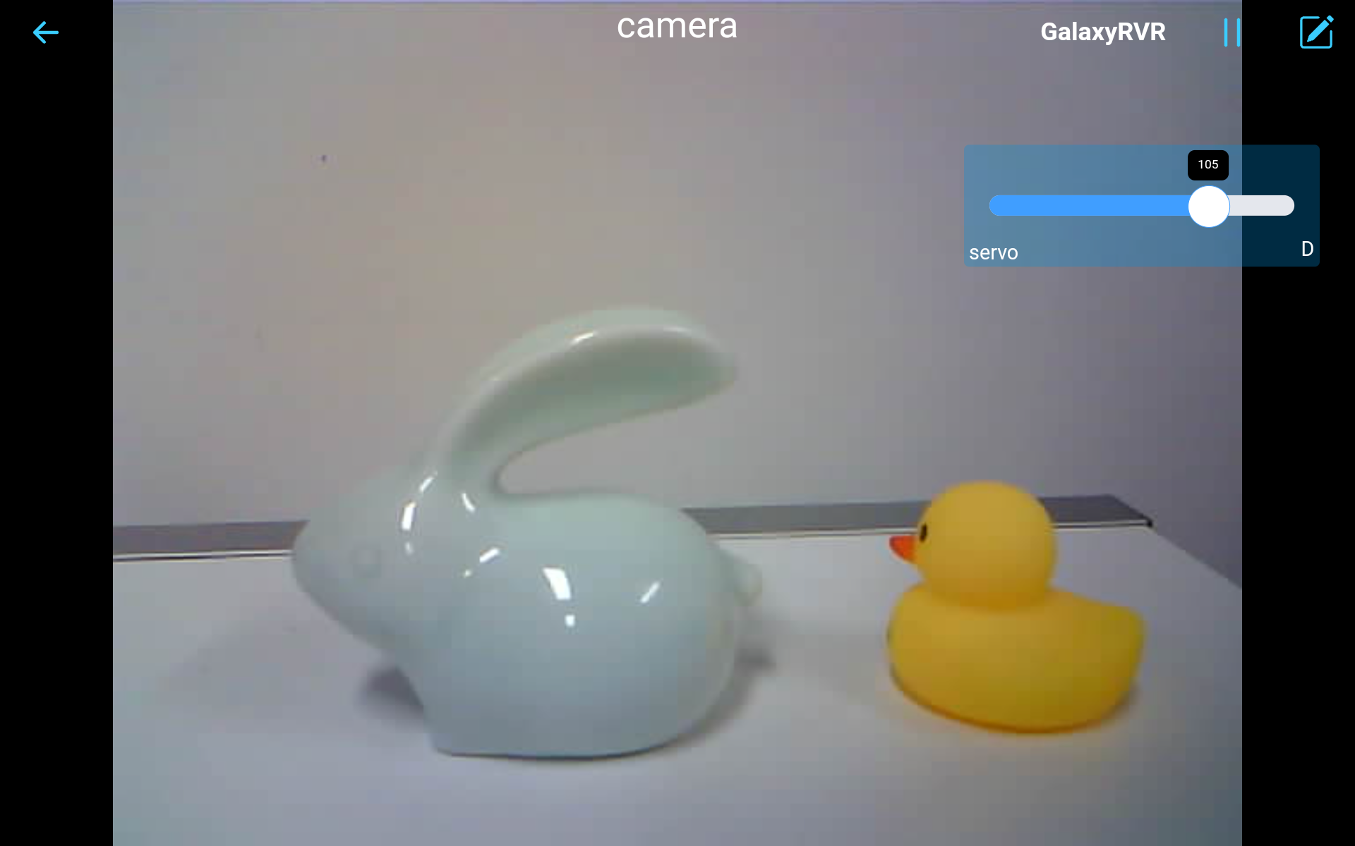
Now, move the slider and open Arduino IDE’s serial monitor simultaneously. You should see similar data like below.
Slider D: 105
WS+null
Slider D: 105
WS+null
Slider D: 105
WS+null
Let the Slider control the tilt mechanism.
- Now that we know the values transmitted by the slider widget, we can directly use these values to rotate the servo.
Therefore, based on the previous code, add the following lines to initialize the servo and write the slider’s value to the servo.
...
#include <Servo.h>

Servo myServo;  // create a servo object
myServo.write(int(sliderD));  // control the servo to move to the current angle

...

void onReceive() {
    ...
    myServo.write(int(sliderD));  // control the servo to move to the current angle
}

void setup() {
    ...
    myServo.attach(6);  // attaches the servo on pin 6
    ...
}
Here is the complete code:
Upload the above code to the GalaxyRVR, repeat steps 4 and 5 above, reconnect to the
GalaxyRVRLAN and re-run in the SunFounder Controller, then you can slide the slider to control the rover’s tilt mechanism.
Now you’ve successfully learned to implement the SunFounder Controller and how to use the slider widget to control servo movements. This process will allow you to interact with your GalaxyRVR in a more intuitive and direct way.
Step 4: Reflection and Summary
Using the SunFounder Controller to operate your Mars Rover may seem a bit complicated at first. Every time you modify your code, you’ll need to repeat the following steps:
Prior to uploading the code, ensure the switch is turned to the right.
Once the code has been successfully uploaded, switch to the left to initiate the ESP32 CAM.
Connect to the
GalaxyRVRNetwork.Connect and run the controller.
Though these steps might seem tedious, they are crucial for the process. After repeating them a few times, you’ll become more familiar and comfortable with the procedure.
Now that we’ve finished this lesson, let’s reflect on what we’ve learned through some questions:
In the process of creating a new controller, you’ve encountered many different types of blocks. Have you considered what their individual functions might be?
Is it possible to use other widgets to control the tilt mechanism?
Or even directly control the Mars Rover’s movements?
Let’s anticipate our exploration of these questions in the next lesson!