Note
Hello, welcome to the SunFounder Raspberry Pi & Arduino & ESP32 Enthusiasts Community on Facebook! Dive deeper into Raspberry Pi, Arduino, and ESP32 with fellow enthusiasts.
Why Join?
Expert Support: Solve post-sale issues and technical challenges with help from our community and team.
Learn & Share: Exchange tips and tutorials to enhance your skills.
Exclusive Previews: Get early access to new product announcements and sneak peeks.
Special Discounts: Enjoy exclusive discounts on our newest products.
Festive Promotions and Giveaways: Take part in giveaways and holiday promotions.
👉 Ready to explore and create with us? Click [here] and join today!
FAQ
1. Why Should I Update the Firmware?
SunFounder continuously improves the GalaxyRVR’s firmware to provide a better experience. We recommend updating the firmware before your first use to ensure everything works smoothly. Updating the firmware ensures:
Bug fixes: Resolves known issues and improves stability.
App compatibility: The latest firmware is required for the RoboPilot app and Mammoth Coding to work correctly.
New features: Firmware updates may add new capabilities and improvements.
Better performance: Optimizations for WiFi connectivity, camera streaming, and motor control.
For step-by-step update instructions, see Update Firmware.
Note
If you prefer not to update the firmware and want to keep using your current configuration, you can refer to the GalaxyRVR v1 Documentation.
2. Unable to Connect to GalaxyRVR?
If you cannot connect to the GalaxyRVR, please check the following:
Check the battery: Look at the battery indicators on the rover. If both LEDs are off, the battery is low. Charge the rover using a Type-C USB cable.
Check the ESP32 CAM: Ensure the ESP32 CAM is properly seated in its slot. If the ESP32 CAM LED is not lit, the camera module may not be receiving power or could be damaged. The ESP32 CAM creates the WiFi hotspot — if it’s not working, no network will appear.
Check the mode switch: Make sure the mode switch is set to Run (not Upload). The WiFi hotspot only works in Run mode.

Reset the R3 board: After switching to Run mode, press the Reset button on the R3 board. The bottom light strip should flash to indicate a successful startup.
Check the WiFi password: The default hotspot name (SSID) is
GalaxyRVRand the password is12345678. Make sure you entered the password correctly.WiFi interference: Other devices on the same WiFi channel may cause connection issues. If you suspect interference, try changing the WiFi channel.
After firmware update: If you just updated the ESP32 CAM firmware and WiFi stopped working, see 12. How to Restore ESP32 CAM to Factory Settings?.
Verify your mobile device’s connection: If you are using GalaxyRVR in AP mode (default), connect your mobile device to the GalaxyRVR hotspot. If you have configured a home Wi-Fi network, ensure your mobile device is connected to the same home Wi-Fi network.
3. The Bottom Light Is Solid Orange and No WiFi Hotspot Appears?
If the GalaxyRVR’s bottom light strip shows a solid orange light and the GalaxyRVR WiFi network does not appear, the cause is a firmware version mismatch:
The ESP32 CAM firmware is still an older version (1.4.x or 1.3.x)
The UNO R3 board firmware has been updated to version 2.x
The version mismatch prevents communication between the ESP32 CAM and the UNO R3
To resolve this, follow these steps in the exact order:
Roll back the UNO R3 firmware to version 1.x first:
Follow the guide in the v1 documentation: GalaxyRVR v1 — How to Upload the galaxy-rvr.ino Code
Update both firmware following the ESP32 CAM → UNO R3 order:
Follow the updated guide: Update Firmware
Note
The order matters — always update the ESP32 CAM first, then the R3 board. Skipping the rollback step or changing the order will not fix the issue.
4. RoboPilot App Can’t Connect?
If the RoboPilot app cannot find or connect to your GalaxyRVR, check the following:
Is the ESP32 CAM firmware up to date? An outdated ESP32 CAM firmware may cause connection issues. Follow 2. Updating the ESP32 CAM Firmware to check and update.
Is the R3 firmware up to date? The R3 board must have the factory communication firmware installed. If you have uploaded custom Arduino code, it will overwrite this firmware and break RoboPilot communication. Follow 3. Updating the R3 Board Firmware to restore it.
Is the mode switch on Run? The mode switch must be set to Run (not Upload) for the WiFi hotspot to work.
Is your mobile device on the correct WiFi network? Connect to the GalaxyRVR hotspot (
GalaxyRVR/12345678), or if you configured a home WiFi, connect to that same network.Try resetting: Switch to Run mode and press the Reset button, then try connecting again.
If none of the above helps, try 12. How to Restore ESP32 CAM to Factory Settings?.
5. Mammoth Coding (Scratch) App Can’t Connect?
If Mammoth Coding cannot connect to your GalaxyRVR, check the following:
Is the ESP32 CAM firmware up to date? The ESP32 CAM handles the WiFi connection that Mammoth Coding relies on. Follow 2. Updating the ESP32 CAM Firmware to ensure it is up to date.
Is the R3 firmware up to date? Mammoth Coding requires the factory communication firmware on the R3 board. If you have uploaded your own Arduino code, the communication firmware is overwritten. Follow 3. Updating the R3 Board Firmware to restore it.
Is the mode switch on Run? The mode switch must be set to Run for the WiFi hotspot to be active.
Is your mobile device on the correct WiFi network? Make sure your device is connected to the GalaxyRVR hotspot or the same home WiFi network configured on the rover.
Note
If you want to use both Arduino programming and Mammoth Coding, keep in mind that you need to re-upload the R3 firmware each time you switch between them.
6. Compilation error: SoftPWM.h or SunFounder_AI_Camera.h: No such file or directory?
If you get a “Compilation error: SoftPWM.h: No such file or directory” prompt, it means you don’t have the SoftPWM library installed.
Please install the two required libraries SoftPWM and SunFounder AI Camera as shown.
For the SunFounder AI Camera library, you need to select “INSTALL ALL” to simultaneously install the required ArduinoJson dependency.

7. avrdude: stk500_getsync() attempt 10 of 10: not in sync: resp=0x6e?
If the following message keeps appearing after clicking the Upload button when the board and port have been selected correctly.
avrdude: stk500_recv(): programmer is not responding
avrdude: stk500_getsync() attempt 1 of 10: not in sync: resp=0x00
avrdude: stk500_recv(): programmer is not responding
avrdude: stk500_getsync() attempt 2 of 10: not in sync: resp=0x00
avrdude: stk500_recv(): programmer is not responding
avrdude: stk500_getsync() attempt 3 of 10: not in sync: resp=0x00
At this point, you need to make sure that the ESP32 CAM is unplugged.
The ESP32-CAM and the Arduino board share the same RX (receive) and TX (transmit) pins. So, before you’re uploading code, you’ll need to first disconnect the ESP32-CAM to avoid any conflicts or potential issues.
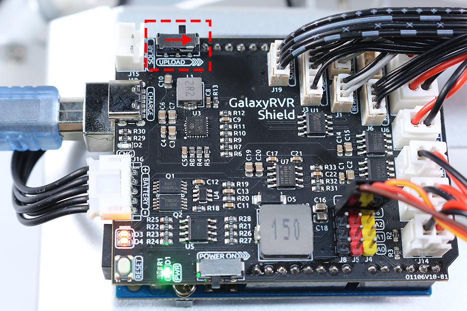
After the code is successfully uploaded, if you need to use the ESP32 CAM, then you need to move the switch to the left to start the ESP32 CAM.
8. How to Change Wi-Fi Channel?
The 2.4GHz Wi-Fi band has channels ranging from 1 to 13. ESP32 supports channels 1 to 11. Other devices operating on the same channel may cause interference, leading to connection issues. To mitigate this, you can try changing the channel. By default, the channel is set to 1. When selecting a new channel, it’s recommended to skip 1-2 channels at a time. For example, if the current channel is 1, try channel 3 first, and if the signal is still poor, proceed to channel 5.
Power on the GalaxyRVR. To activate the ESP32 CAM, move the mode switch to the Run position, and press the reset button to reboot the R3 board.
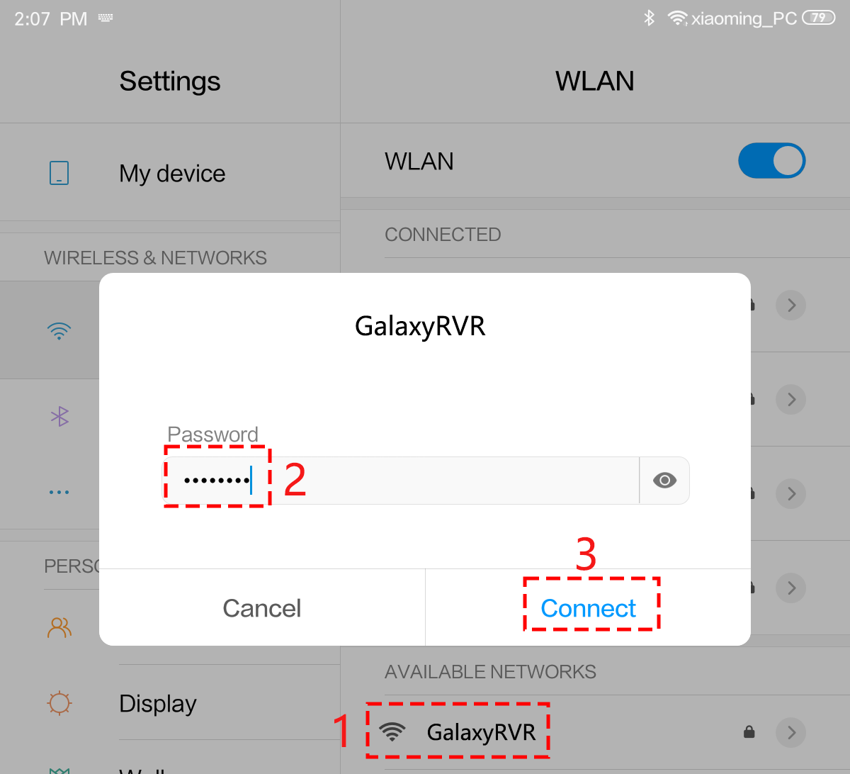
Connect your mobile device to the GalaxyRVR’s WiFi network.
The network name (SSID) is
GalaxyRVRand the password is12345678.If you see a warning stating “No Internet access,” please choose the option to “Stay connected.”
Open a web browser on your mobile device and go to the address
http://192.168.4.1. This will take you to the ESP32-CAM firmware update portal.
Under the AP page, select a different channel.
The default channel is 1. When selecting a new channel, skip 1-2 channels at a time (e.g., from channel 1 to 3, and if needed, to 5).

Return to the Base page and click the Reboot button to restart the GalaxyRVR. The GalaxyRVR is now ready for normal operation.

9. How to Update Firmware for ESP32 CAM
To ensure app compatibility and optimal performance, please make sure your ESP32 CAM firmware is up to date.
For detailed step-by-step instructions, please refer to: 2. Updating the ESP32 CAM Firmware
10. How to Restore the R3 Firmware
The GalaxyRVR’s R3 board comes with firmware that supports both the RoboPilot App and Mammoth Coding.
If you have overwritten this firmware and need to restore communication, follow 3. Updating the R3 Board Firmware.
11. How to Set Up Wi-Fi Connection
By default, GalaxyRVR operates in AP mode, where it creates its own Wi-Fi hotspot that other devices can connect to.
If you want GalaxyRVR to connect to your home Wi-Fi network, follow the steps below:
Power on the GalaxyRVR. To activate the ESP32 CAM, move the mode switch to the Run position, and press the reset button to reboot the R3 board.
Connect your mobile device to the GalaxyRVR’s WiFi network.
The network name (SSID) is
GalaxyRVRand the password is12345678.If you see a warning stating “No Internet access,” please choose the option to “Stay connected.”
Open a web browser on your mobile device and go to the address
http://192.168.4.1. This will take you to the ESP32-CAM firmware update portal.
Under the WiFi page, enter your home WiFi network name (SSID) and password.

Tap the CONFIRM button.
GalaxyRVR will attempt to connect to your home Wi-Fi.
If the connection is successful, the spinning icon will stop and a checkmark will appear.
After rebooting, connect your mobile device to the same home Wi-Fi network.
You can now connect to GalaxyRVR through the RoboPilot App or Mammoth Coding.
12. How to Restore ESP32 CAM to Factory Settings?
If the GalaxyRVR’s WiFi hotspot does not appear or you cannot connect after updating the ESP32 CAM firmware, the old WiFi configuration data stored in the ESP32 CAM’s flash memory may be causing a conflict.
To resolve this, you need to restore the ESP32 CAM to its factory settings by clearing the stored data. This is done by shorting the IO13 and IO15 pins on the ESP32 CAM:
Turn off the GalaxyRVR’s power switch.
Locate the IO13 and IO15 pins on the ESP32 CAM module.
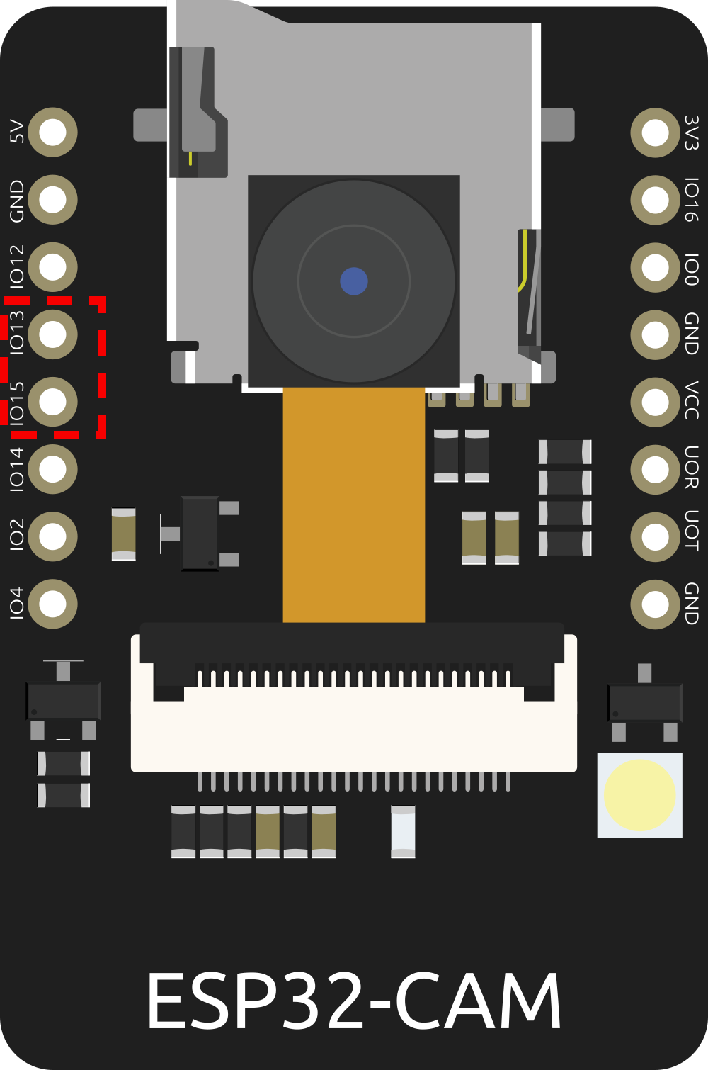
Use a jumper wire or tweezers to short (connect) the IO13 and IO15 pins together.
While keeping the pins shorted, turn on the GalaxyRVR’s power switch.
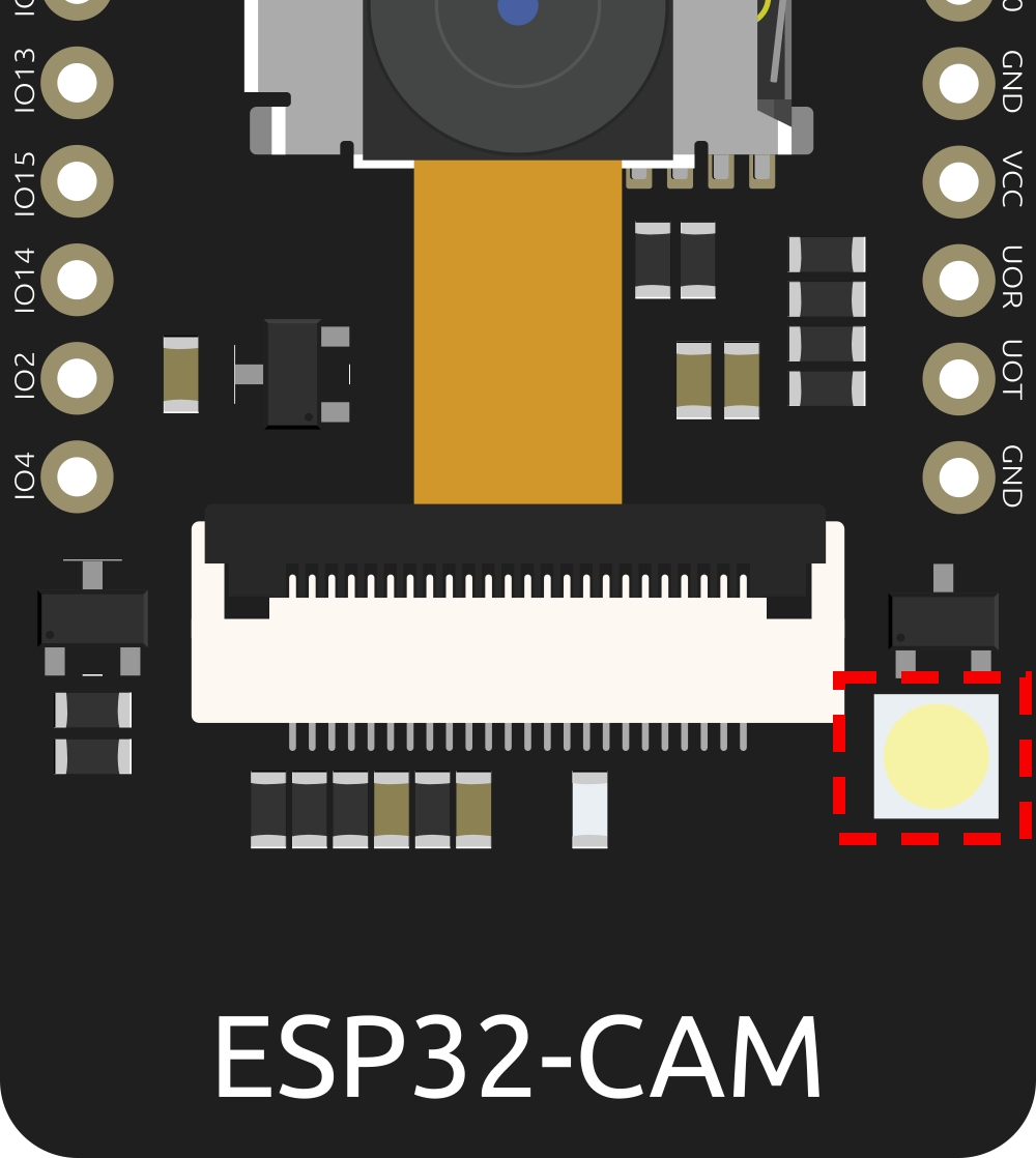
Watch the ESP32 CAM LED — when it flashes twice quickly, remove the jumper wire.
Switch the mode to Run and press the Reset button on the R3 board.
The ESP32 CAM will now boot with its configuration cleared. You should see a hotspot named
AI Camera-xxxxxx(wherexxxxxxis a unique identifier) on your device’s WiFi list. Connect using the password12345678.After restarting the GalaxyRVR, the hotspot name will change from
AI Camera-xxxxxxback toGalaxyRVR-xxxxxx, indicating the factory settings have been successfully restored.
Note
After restoring factory settings, you will need to reconfigure any previously saved home WiFi settings (11. How to Set Up Wi-Fi Connection).