Note
Hello, welcome to the SunFounder Raspberry Pi & Arduino & ESP32 Enthusiasts Community on Facebook! Dive deeper into Raspberry Pi, Arduino, and ESP32 with fellow enthusiasts.
Why Join?
Expert Support: Solve post-sale issues and technical challenges with help from our community and team.
Learn & Share: Exchange tips and tutorials to enhance your skills.
Exclusive Previews: Get early access to new product announcements and sneak peeks.
Special Discounts: Enjoy exclusive discounts on our newest products.
Festive Promotions and Giveaways: Take part in giveaways and holiday promotions.
👉 Ready to explore and create with us? Click [here] and join today!
Lesson 7 Tilt Switch
Introduction
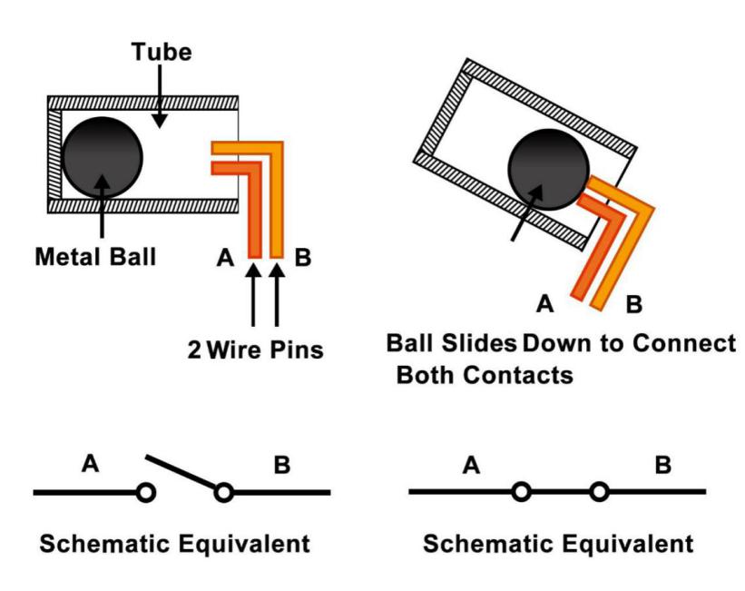
The tilt switch used here is a ball one with a metal ball inside. It is used to detect inclinations of a small angle.
Components
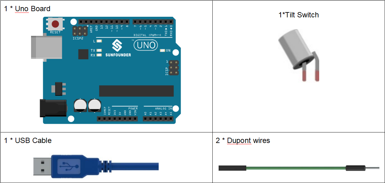
Experimental Principle
The principle is very simple. When the switch is tilted in a certain angle, the ball inside rolls down and touches the two contacts connected to the pins outside, thus triggering circuits. Otherwise the ball will stay away from the contacts, thus breaking the circuits.
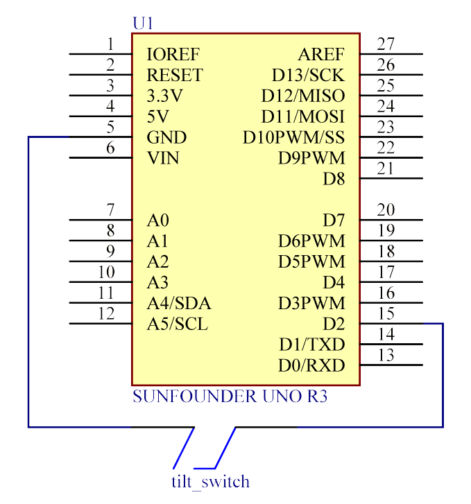
The schematic diagram:
Experimental Procedures
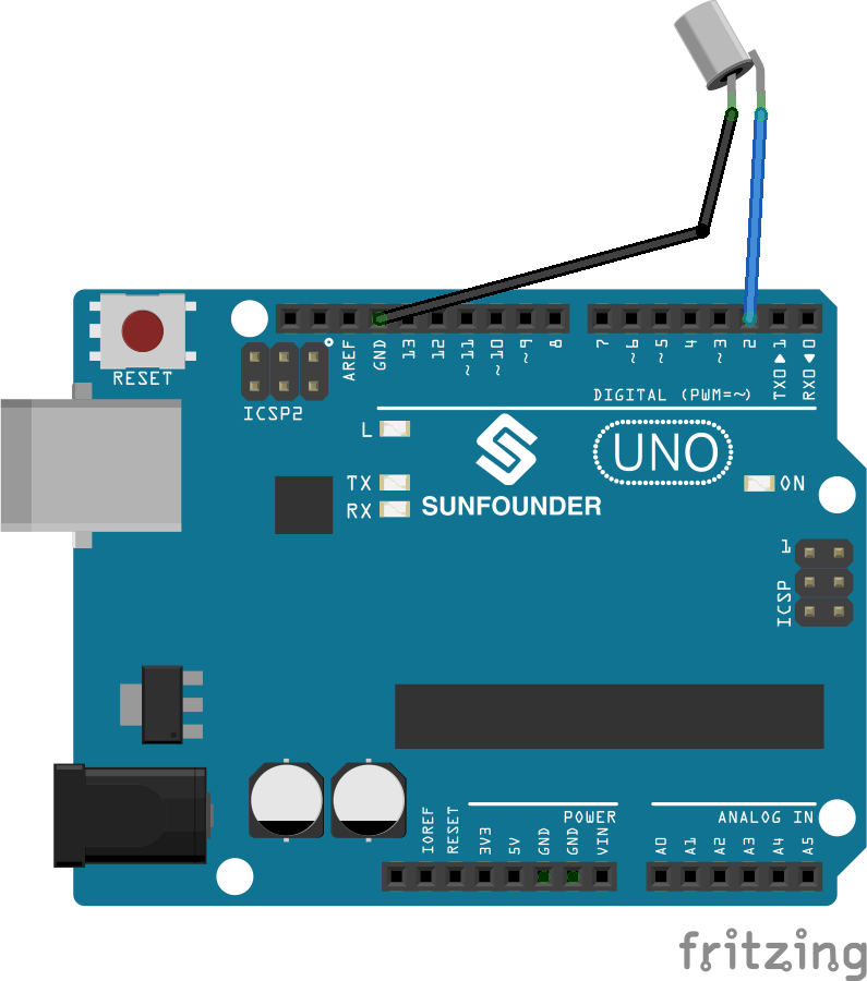
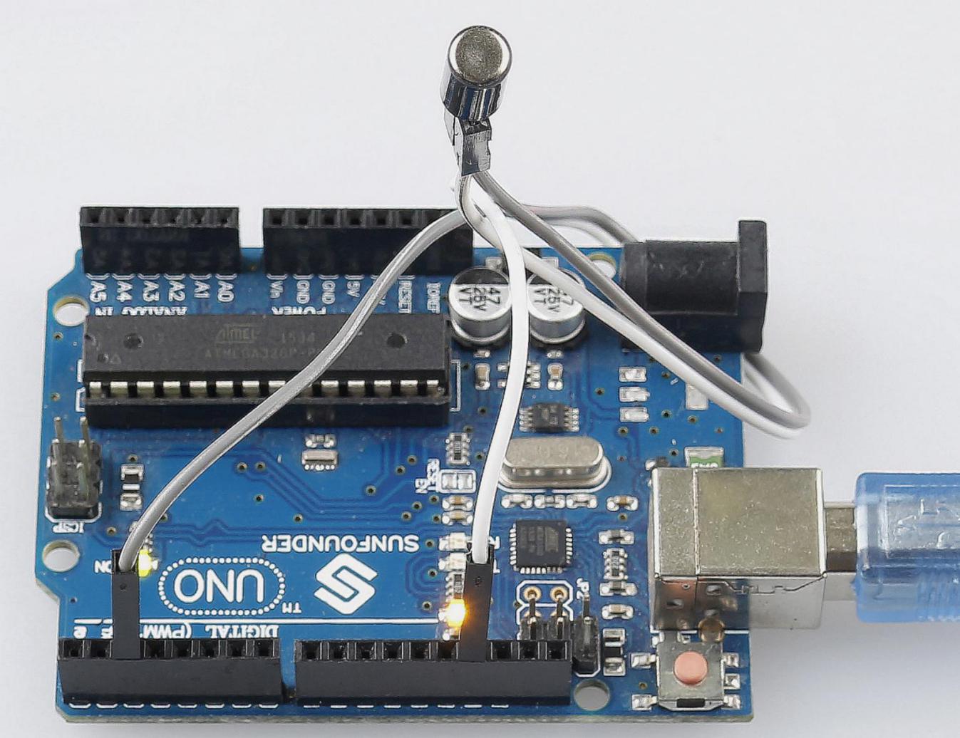
Step 1: Build the circuit
Step 2: Open the code file.
Step 3: Select the Board and Port.
Step 4: Upload the sketch to the board.
Now, tilt the switch, and the LED attached to pin 13 on Uno board will light up.
Code
Code Analysis 7-1 Whole Code
const int ledPin = 13;      // the led attach to

void setup()

{

    pinMode(ledPin,OUTPUT); // initialize the ledPin as an output

    pinMode(2,INPUT);       // set pin2 as INPUT

    digitalWrite(2, HIGH);  // set pin2 as HIGH

}

/******************************************/

void loop()

{

    int digitalVal = digitalRead(2); // Read the value of pin2

    if(HIGH == digitalVal)           // if tilt switch is not breakover

    {

        digitalWrite(ledPin,LOW);    // turn the led off

    }

    else //if tilt switch breakover

    {

        digitalWrite(ledPin,HIGH);   // turn the led on

    }

}
The whole code are very simple, one pin of the tilt switch is connected to pin2, another pin is connected to GND, when tilt the switch, the two pins of the switch will be connected to GND, then let the LED on the pin13 lights up.