Note
Hello, welcome to the SunFounder Raspberry Pi & Arduino & ESP32 Enthusiasts Community on Facebook! Dive deeper into Raspberry Pi, Arduino, and ESP32 with fellow enthusiasts.
Why Join?
Expert Support: Solve post-sale issues and technical challenges with help from our community and team.
Learn & Share: Exchange tips and tutorials to enhance your skills.
Exclusive Previews: Get early access to new product announcements and sneak peeks.
Special Discounts: Enjoy exclusive discounts on our newest products.
Festive Promotions and Giveaways: Take part in giveaways and holiday promotions.
👉 Ready to explore and create with us? Click [here] and join today!
Lesson 12 Servo
Introduction
Servo is a type of geared motor that can only rotate 180 degrees. It is controlled by sending electrical pulses from your board. These pulses tell the servo what position it should move to.
A servo has three wires: the brown wire is GND, the red one is VCC, and the orange one is signal line.
Components

Experimental Principle
Servo
A servo is generally composed of the following parts: case, shaft, gear train, adjustable potentiometer, DC motor, and control circuit board.
It works like this: The Uno board sends out PWM signals to the servo, and then the control circuit in the servo receives the signals through the signal pin and controls the motor inside to turn. As a result, the motor drives the gear chain and then motivates the shaft after deceleration. The shaft and adjustable potentiometer of the servo are connected together. When the shaft rotates, it drives the pot, so the pot outputs a voltage signal to the circuit board. Then the board determines the direction and speed of rotation based on the current position, so it can stop exactly at the right position as defined and hold there.
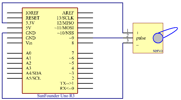
The schematic diagram:
Experimental Procedures
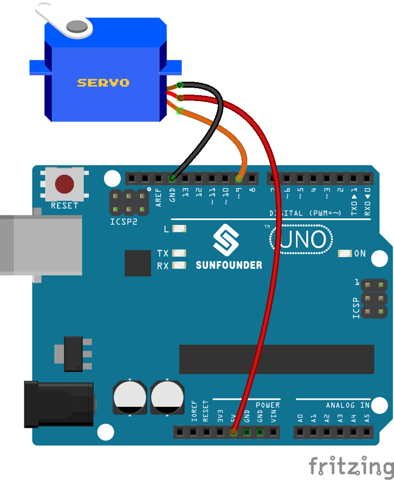
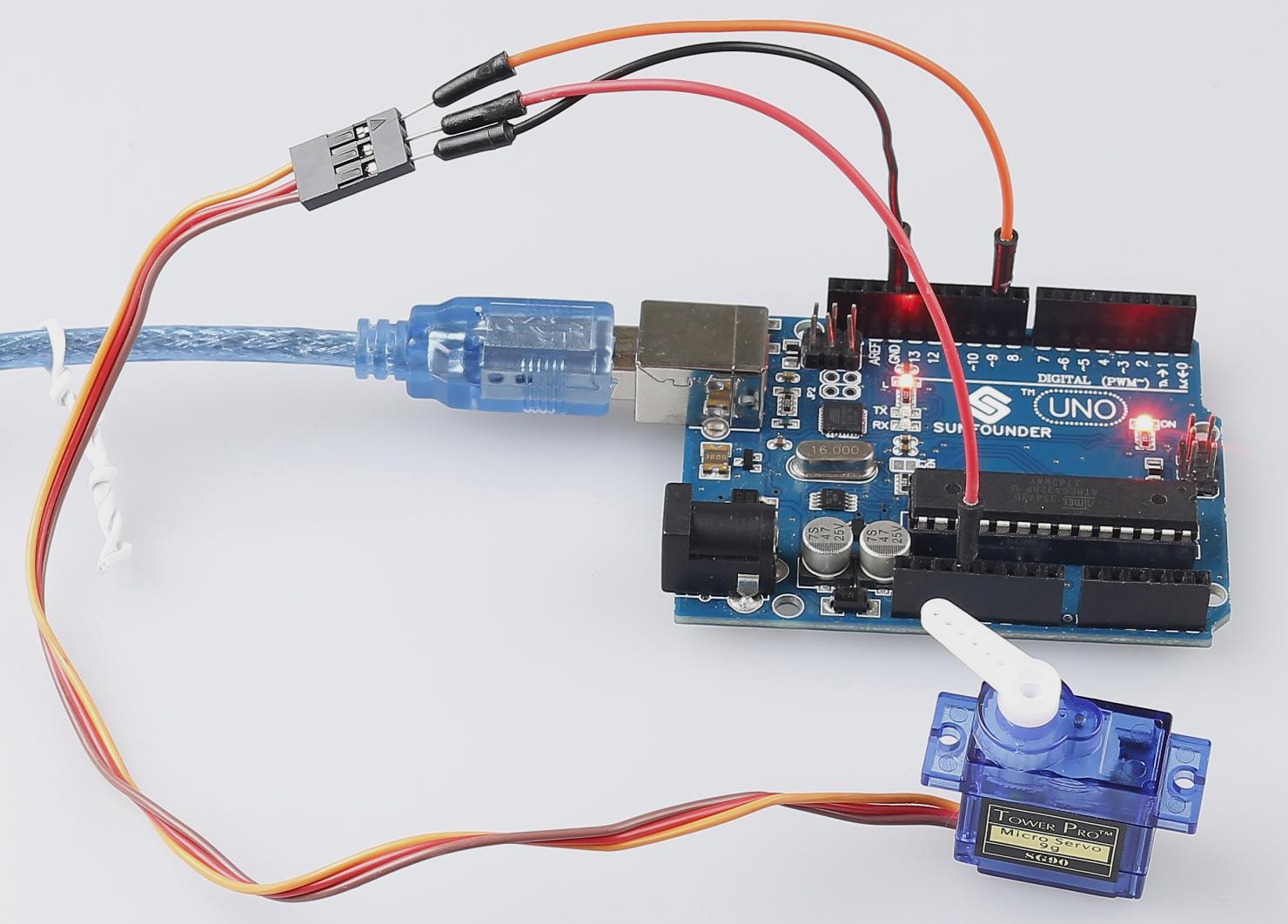
Step 1: Build the circuit. (Brown to GND, Red to VCC, Orange to pin 9 of the control board)
Step 2: Open the code file.
Step 3: Select the Board and Port.
Step 4: Upload the sketch to the board.
Now, you can see the rocker arm of the servo rotate and stop at 90 degrees (15 degrees each time). And then it rotates in the opposite direction.
Code
Code Analysis 12-1 Include a library
#include <Servo.h>
Servo myservo;     //create servo object to control a servo
With the Servo.h file included, you can call the functions in this file later. Servo is a built-in library in the Arduino IDE. You can find the Servo folder under the installation path C:\Program Files\Arduino\libraries.
Code Analysis 12-2 Initialize the servo
{

    myservo.attach(9);  //attachs the servo on pin 9 to servo object

    myservo.write(0);   //back to 0 degrees

    delay(1000);        //wait for a second

}
myservo.attach(): Attach the Servo variable to a pin. Initialize the servo attach to pin9.
myservo.write(): Writes a value to the servo, controlling the shaft accordingly. On a standard servo, this will set the angle of the shaft (in degrees), moving the shaft to that orientation. Here let the servo stay in the 0 angle firstly.
Code Analysis 12-3 Servo rotate
void loop()

{

    for (int i = 0; i <= 180; i++)

    {

        myservo.write(i);   //write the i angle to the servo

        delay(15);          //delay 15ms

    }

    for (int i = 180; i >= 0; i--)

    {

        myservo.write(i);   //write the i angle to the servo

        delay(15);          //delay 15ms

    }

}
Use 2 for() statement to write 0 - 180 to the servo, so that you can see the servo rotate from 0 to 180 angle, then turn back to 0.