Note
Hello, welcome to the SunFounder Raspberry Pi & Arduino & ESP32 Enthusiasts Community on Facebook! Dive deeper into Raspberry Pi, Arduino, and ESP32 with fellow enthusiasts.
Why Join?
Expert Support: Solve post-sale issues and technical challenges with help from our community and team.
Learn & Share: Exchange tips and tutorials to enhance your skills.
Exclusive Previews: Get early access to new product announcements and sneak peeks.
Special Discounts: Enjoy exclusive discounts on our newest products.
Festive Promotions and Giveaways: Take part in giveaways and holiday promotions.
👉 Ready to explore and create with us? Click [here] and join today!
Lesson 4 Doorbell
Introduction
A buzzer is a great tool in your experiments whenever you want to make some sounds. In this lesson, we will learn how to drive an active buzzer to build a simple doorbell.
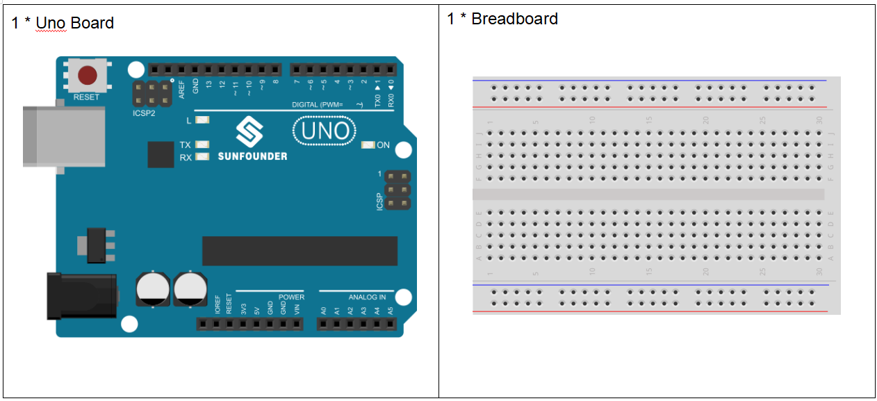
Components
Experimental Principle
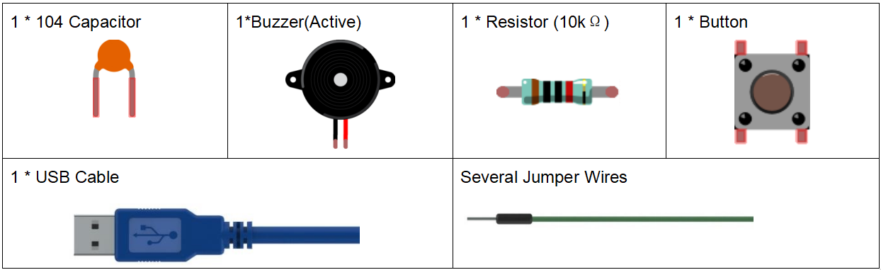
As a type of electronic buzzer with an integrated structure, buzzers, which are supplied by DC power, are widely used in computers, printers, photocopiers, alarms, electronic toys, automotive electronic devices, telephones, timers and other electronic products for voice devices. Buzzers can be categorized as active and passive ones (see the following picture). Turn the pins of two buzzers face up, and the one with a green circuit board is a passive buzzer, while the other enclosed with a black tape is an active one.
The difference between an active buzzer and a passive buzzer:
An active buzzer has a built-in oscillating source, so it will make sounds when electrified. But a passive buzzer does not have such source, so it will not tweet if DC signals are used; instead, you need to use square waves whose frequency is between 2K and 5K to drive it. The active buzzer is often more expensive than the passive one because of multiple built-in oscillating circuits.
In this experiment, we use an active buzzer.
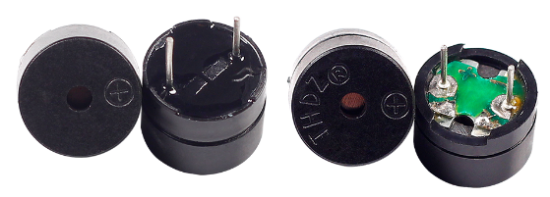
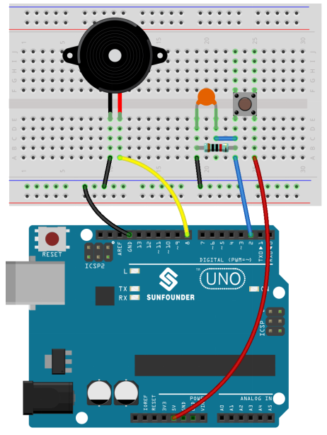
The schematic diagram:
Experimental Procedures
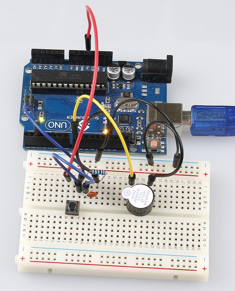
Step 1: Build the circuit (Long pins of buzzer is the Anode and the short pin is Cathode).
Step 2: Open the code file.
Step 3: Select the Board and Port.
Step 4: Upload the sketch to the board.
Now, you should hear the buzzer beep.
Code
Code Analysis 4-1 Define variables
const int buttonPin = 2; //the button connect to pin2

const int buzzerPin = 8; //the led connect to pin8

/**********************************/

int buttonState = 0; //variable for reading the pushbutton status
Connect the button to pin 2 and buzzer to pin 8. Define a variable buttonState to restore the state of the button.
Code Analysis 4-2 Set the input and output status of the pins
void setup()

{

    pinMode(buttonPin, INPUT); //initialize the buttonPin as input

    pinMode(buzzerPin, OUTPUT); //initialize the buzzerpin as output

}
We need to know the status of the button in this experiment, so here set the buttonPin as INPUT; to set HIGH/LOW of the buzzer, we set buzzerPin as OUTPUT.