Note
Hello, welcome to the SunFounder Raspberry Pi & Arduino & ESP32 Enthusiasts Community on Facebook! Dive deeper into Raspberry Pi, Arduino, and ESP32 with fellow enthusiasts.
Why Join?
Expert Support: Solve post-sale issues and technical challenges with help from our community and team.
Learn & Share: Exchange tips and tutorials to enhance your skills.
Exclusive Previews: Get early access to new product announcements and sneak peeks.
Special Discounts: Enjoy exclusive discounts on our newest products.
Festive Promotions and Giveaways: Take part in giveaways and holiday promotions.
👉 Ready to explore and create with us? Click [here] and join today!
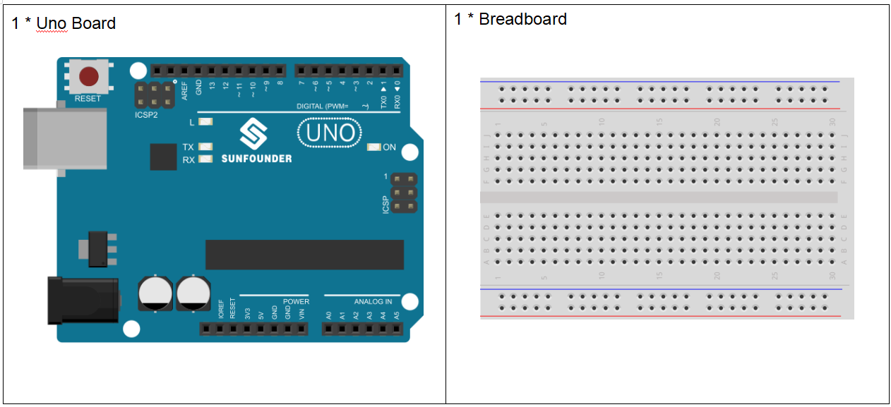
Lesson 17 Light Alarm
Introduction
This experiment is a very interesting one – a DIY phototransistor. DIY phototransistors use the glow effect and photoelectric effect of LEDs. That is, LEDs will generate weak currents when some light is shined on it. And we use a transistor to amplify the currents generated, so the SunFounder Uno board can detect them.
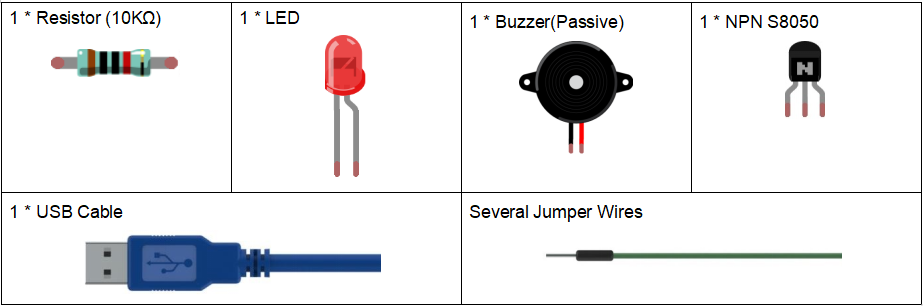
Components
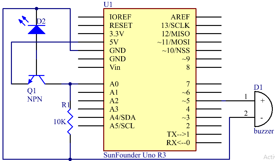
Experimental Principle
LEDs not only have a glow effect, but also a photoelectric effect. They will generate weak currents when exposed to light waves.
NPN consists of a layer of P-doped semiconductor (the “base”) between two N-doped layers (see the picture above). A small current entering the base is amplified to produce a large collector and emitter current. That is, when there is a positive potential difference measured from the emitter of a NPN transistor to its base (i.e., when the base is high relative to the emitter) as well as positive potential difference measured from the base to the collector, the transistor becomes active. In this “on” state, current flows between the collector and emitter of the transistor.
A 10kΩ pull-down resistor is attached to the transistor output stage in order to avoid analog port suspending to interfere with signals and cause misjudgment.
When the LED exposed to light waves, the LED generates weak currents, then the NPN transistor becomes active. Then read the analog value of A0, when A0>0, then set pin 5(buzzer) to high level.
The schematic diagram:
Experimental Procedures
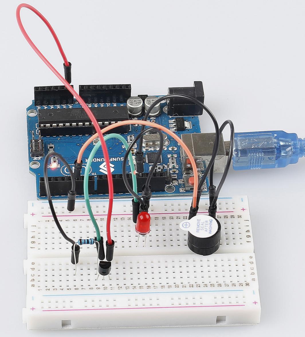
Step 1: Build the circuit.
Step 2: Open the code file
Step 3: Select the correct Board and Port
Step 4: Upload the sketch to the board
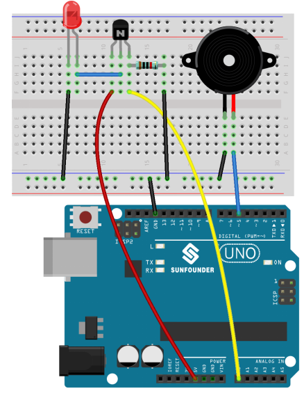
Now, you can hear the buzzer beep when shining a flashlight on the LED.
Note
You need to do this experiment in a dark environment, or the lights you give need to be much stronger than ambient light.
Code
Code Analysis 17-1 Whole Code
void setup()

{

    Serial.begin(9600);    // start serial port at 9600 bps:

}

void loop()

{

    int n=analogRead(A0); //read the value from analog pin AO

    Serial.println(n);

    if(n>0) //If there is a voltage

    {

        pinMode(5,OUTPUT); //set the digital pin 5 as an output

        tone(5,10000);
        //Generates a square wave of the frequency of 10000 Hz (and 50% duty cycle) on pin 5

        pinMode(5,INPUT); //set the pin 5 as an input

    }

}
tone()
Description
Generates a square wave of the specified frequency (and 50% duty cycle) on a pin. A duration can be specified, otherwise the wave continues until a call to noTone(). The pin can be connected to a piezo buzzer or other speaker to play tones.
Only one tone can be generated at a time. If a tone is already playing on a different pin, the call to tone() will have no effect. If the tone is playing on the same pin, the call will set its frequency.
Use of the tone() function will interfere with PWM output on pins 3 and 11 (on boards other than the Mega).
Syntax
tone(pin, frequency)
tone(pin, frequency, duration)
Parameters
pin: the pin on which to generate the tone
frequency: the frequency of the tone in hertz - unsigned int
duration: the duration of the tone in milliseconds (optional) - unsigned long