Note
Hello, welcome to the SunFounder Raspberry Pi & Arduino & ESP32 Enthusiasts Community on Facebook! Dive deeper into Raspberry Pi, Arduino, and ESP32 with fellow enthusiasts.
Why Join?
Expert Support: Solve post-sale issues and technical challenges with help from our community and team.
Learn & Share: Exchange tips and tutorials to enhance your skills.
Exclusive Previews: Get early access to new product announcements and sneak peeks.
Special Discounts: Enjoy exclusive discounts on our newest products.
Festive Promotions and Giveaways: Take part in giveaways and holiday promotions.
👉 Ready to explore and create with us? Click [here] and join today!
1.3.4 Relay
Introduction
In this project, we will learn to use a relay. It is one of the commonly used components in automatic control system. When the voltage, current, temperature, pressure, etc., reaches, exceeds or is lower than the predetermined value, the relay will connect or interrupt the circuit, to control and protect the equipment.
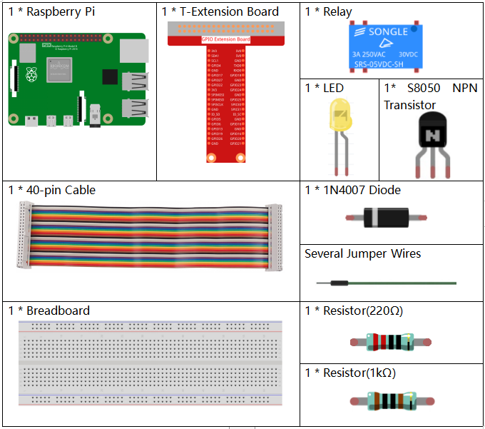
Required Components
In this project, we need the following components.
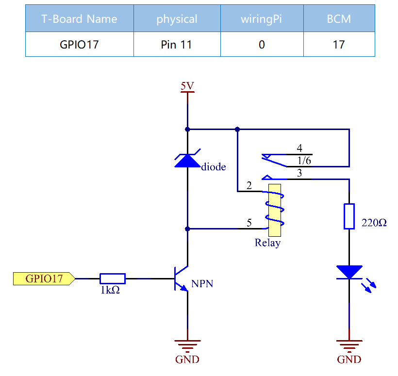
Schematic Diagram
Experimental Procedures
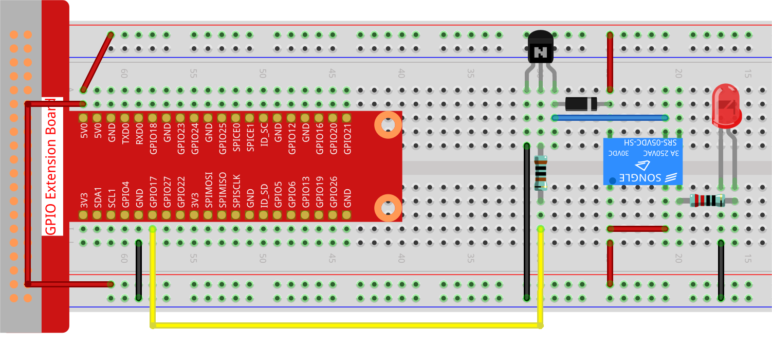
Step 1: Build the circuit.
Step 2: Open the code file.
cd ~/davinci-kit-for-raspberry-pi/python-pi5
Step 3: Run.
sudo python3 1.3.4_Relay.py
While the code is running, the LED lights up. In addition, you can hear a ticktock caused by breaking normally close contact and closing normally open contact.
Warning
If there is an error prompt RuntimeError: Cannot determine SOC peripheral base address, please refer to If gpiozero doesn’t work.
Code
Note
You can Modify/Reset/Copy/Run/Stop the code below. But before that, you need to go to source code path like davinci-kit-for-raspberry-pi/python-pi5. After modifying the code, you can run it directly to see the effect.
#!/usr/bin/env python3
from gpiozero import OutputDevice  # Import the class for controlling GPIO pins
from time import sleep  # Import the sleep function for delay

# Initialize the relay connected to GPIO pin 17
relay = OutputDevice(17)

try:
    # Loop to continuously toggle the relay's state every second
    while True:
        print('Relay open...')  # Inform that the relay is being activated
        relay.on()  # Turn on the relay (assuming active low configuration)
        sleep(1)   # Maintain the relay in the on state for 1 second

        print('...Relay close')  # Inform that the relay is being deactivated
        relay.off()  # Turn off the relay
        sleep(1)   # Maintain the relay in the off state for 1 second

except KeyboardInterrupt:
    # Handle a keyboard interrupt (Ctrl+C) to exit the loop
    relay.off()  # Ensure the relay is turned off before exiting
    pass
Code Explanation
It imports
OutputDevicefromgpiozerofor controlling GPIO pins andsleepfromtimefor adding delays.#!/usr/bin/env python3 from gpiozero import OutputDevice # Import the class for controlling GPIO pins from time import sleep # Import the sleep function for delay
Initializes an
OutputDeviceobject for the relay connected to GPIO pin 17.# Initialize the relay connected to GPIO pin 17 relay = OutputDevice(17)
Inside the
tryblock, awhile Trueloop continuously toggles the relay’s state. The relay is turned on and off with a 1-second delay between each state, accompanied by console print statements.try: # Loop to continuously toggle the relay's state every second while True: print('Relay open...') # Inform that the relay is being activated relay.on() # Turn on the relay (assuming active low configuration) sleep(1) # Maintain the relay in the on state for 1 second print('...Relay close') # Inform that the relay is being deactivated relay.off() # Turn off the relay sleep(1) # Maintain the relay in the off state for 1 second
Catches a KeyboardInterrupt (like Ctrl+C) to allow for graceful script termination. The relay is turned off before exiting the script.
except KeyboardInterrupt:
# Handle a keyboard interrupt (Ctrl+C) to exit the loop
relay.off()  # Ensure the relay is turned off before exiting
pass