Note
Hello, welcome to the SunFounder Raspberry Pi & Arduino & ESP32 Enthusiasts Community on Facebook! Dive deeper into Raspberry Pi, Arduino, and ESP32 with fellow enthusiasts.
Why Join?
Expert Support: Solve post-sale issues and technical challenges with help from our community and team.
Learn & Share: Exchange tips and tutorials to enhance your skills.
Exclusive Previews: Get early access to new product announcements and sneak peeks.
Special Discounts: Enjoy exclusive discounts on our newest products.
Festive Promotions and Giveaways: Take part in giveaways and holiday promotions.
👉 Ready to explore and create with us? Click [here] and join today!
LED Dot Matrix
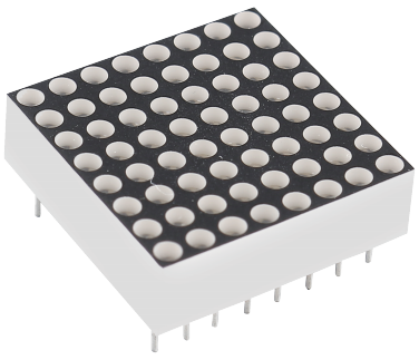
The LED dot matrix can be divided into two types: Common Cathode (CC) and Common Anode (CA). They look similar on the outside, but their internal electrical structure is different.
The LED dot matrix used in this kit is a Common Anode (CA) type. You can identify it by the marking “788BS” printed on the side of the module.
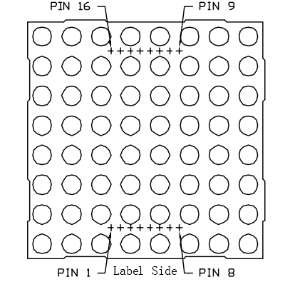
Pin Layout
The pins are located on both sides of the back of the module. When facing the side with the label:
Pins 1–8 are on one side
Pins 9–16 are on the opposite side
External view:
Internal Structure
The following figure shows the internal structure of the LED dot matrix.
In a Common Anode (CA) matrix, ROW = Anode and COL = Cathode
In a Common Cathode (CC) matrix, ROW = Cathode and COL = Anode
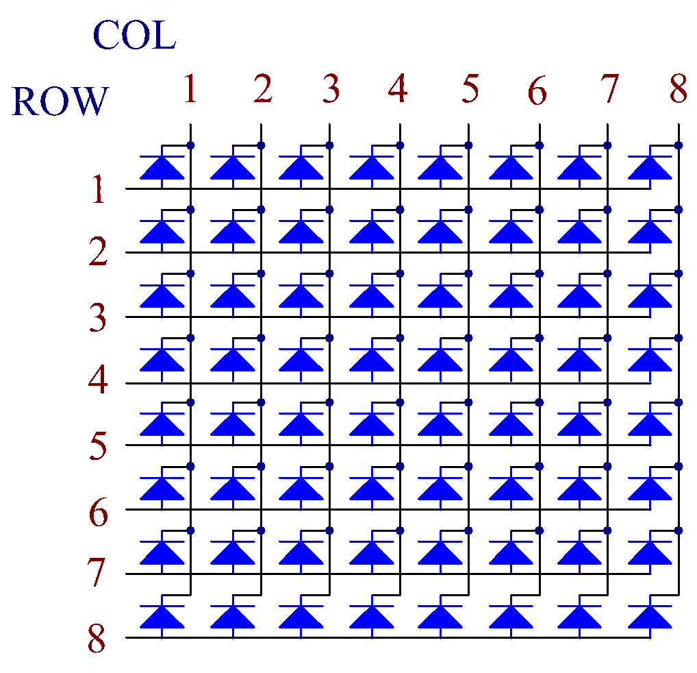
For both CA and CC types, the physical pin positions for rows and columns are the same — only the electrical polarity is different.
Pin Mapping
COL |
1 |
2 |
3 |
4 |
5 |
6 |
7 |
8 |
|---|---|---|---|---|---|---|---|---|
Pin No. |
13 |
3 |
4 |
10 |
6 |
11 |
15 |
16 |
ROW |
1 |
2 |
3 |
4 |
5 |
6 |
7 |
8 |
Pin No. |
9 |
14 |
8 |
12 |
1 |
7 |
2 |
5 |
How LEDs Are Turned On
To control a single LED, you must activate its ROW and COL pins correctly.
Example: top-left LED (ROW 1, COL 1)
CA type Set ROW pin 9 = High, COL pin 13 = Low
CC type Set COL pin 13 = High, ROW pin 9 = Low
Example: light up the entire first column
CA type Set COL pin 13 = Low Set ROW pins 9, 14, 8, 12, 1, 7, 2, 5 = High
CC type Set COL pin 13 = High Set ROW pins 9, 14, 8, 12, 1, 7, 2, 5 = Low
This row-column scanning method allows you to control each LED individually using multiplexing.