1.4 Connecting the R3 board to Blynk
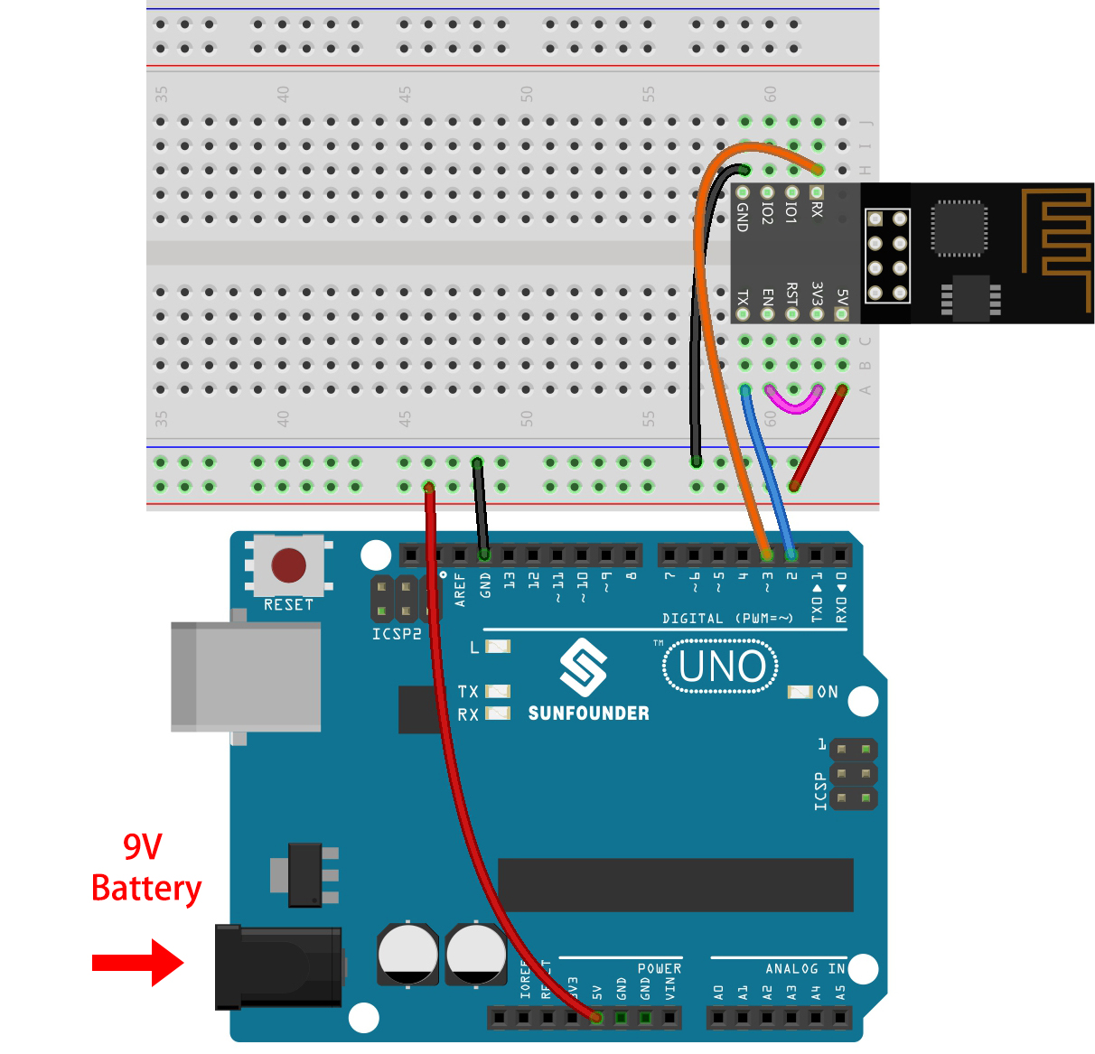
Reconnect the ESP8266 module and R3 board, here the software serial is used, so TX and RX are connected to pins 2 and 3 of R3 board respectively.
Note
The ESP8266 module requires a high current to provide a stable operating environment, so make sure the 9V battery is plugged in.
Open the
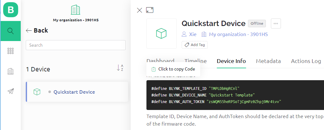
1.connect.inofile under the path of3in1-kit\iot_project\1.connect. Or copy this code into Arduino IDE.Replace the following three lines of code that you can copy from your account’s Device info page. These three lines of code will allow your R3 board to find your blynk account.
#define BLYNK_TEMPLATE_ID "TMPLxxxxxx"
#define BLYNK_DEVICE_NAME "Device"
#define BLYNK_AUTH_TOKEN "YourAuthToken"
Fill in the
ssidandpasswordof the WiFi you are using.char ssid[] = "ssid"; char pass[] = "password";
Upload the code to the R3 board, then open the serial monitor and set the baud rate to 115200. when the R3 board communicates with Blynk successfully, the serial monitor will show the
readycharacter.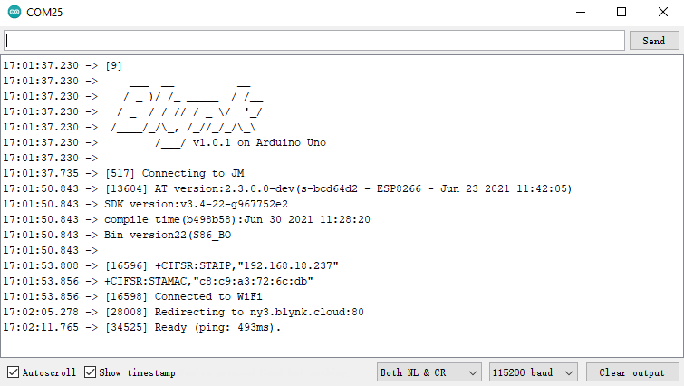
Note
If the message
ESP is not respondingappears when you connect, please follow these steps.Make sure the 9V battery is plugged in.
Reset the ESP8266 module by connecting the pin RST to GND for 1 second, then unplug it.
Press the reset button on the R3 board.
Sometimes, you may need to repeat the above operation 3-5 times, please be patient.
The status of Blynk will change from offline to online.