7. Current Limiting Gate
Some situations, such as parking lots, require quantity management.
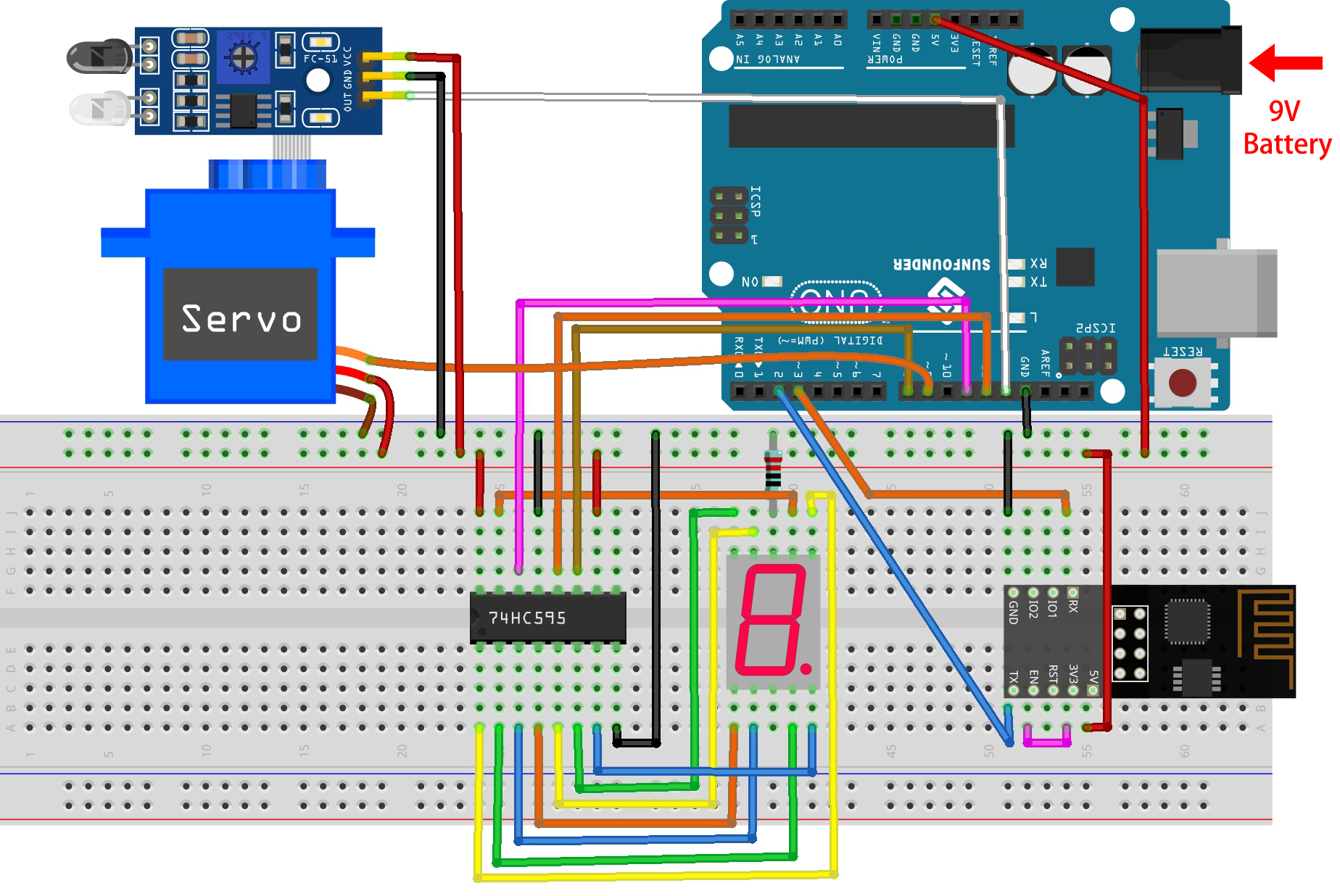
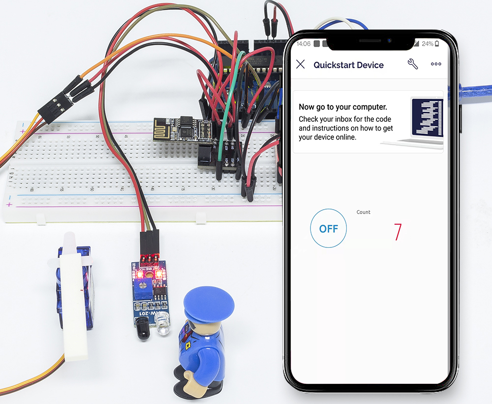
Here we create a smart gate: a servo is used as the gate, and an IR obstacle detector is placed in front of it; if an object (like a car) is detected, the gate will open and the number will be increased by 1. The count is displayed with a 7-segment display and is also uploaded to the Blynk Cloud for you to view remotely. Finally, Blynk has a Switch widget to enable or disable this smart gate system.
Required Components
In this project, we need the following components.
It’s definitely convenient to buy a whole kit, here’s the link:
Name |
ITEMS IN THIS KIT |
LINK |
|---|---|---|
3 in 1 Starter Kit |
380+ |
You can also buy them separately from the links below.
COMPONENT INTRODUCTION |
PURCHASE LINK |
|---|---|
1. Build the Cirduit
Note
The ESP8266 module requires a high current to provide a stable operating environment, so make sure the 9V battery is plugged in.
2. Edit Dashboard
To record the number, create a Datastream of type Virtual Pin on the Datastream page. Set DATA TYPE to
Integerand MIN and MAX to0and10.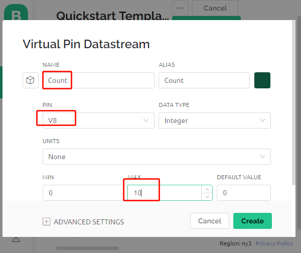
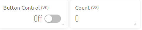
Now go to the Wed Dashboard page, drag a Switch widget to set its data stream to V0 and a Label widget to set its data stream to V8.
3. Run the Code
Open the
7.current_limiting_gate.inofile under the path of3in1-kit\iot_project\7.current_limiting_gate, or copy this code into Arduino IDE.Replace the
Template ID,Device Name, andAuth Tokenwith your own. You also need to enter thessidandpasswordof the WiFi you are using. For detailed tutorials, please refer to 1.4 Connecting the R3 board to Blynk.After selecting the correct board and port, click the Upoad button.
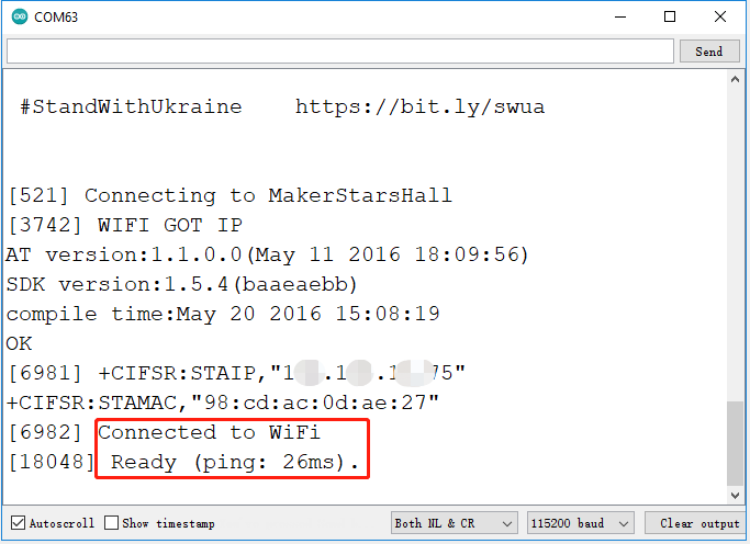
Open the Serial monitor(set baudrate to 115200) and wait for a prompt such as a successful connection to appear.
Note
If the message
ESP is not respondingappears when you connect, please follow these steps.Make sure the 9V battery is plugged in.
Reset the ESP8266 module by connecting the pin RST to GND for 1 second, then unplug it.
Press the reset button on the R3 board.
Sometimes, you may need to repeat the above operation 3-5 times, please be patient.
Now click on the Button Control widget on Blynk to enable the smart door system. If the IR obstacle avoidance module detects an obstacle, the gate will open and the 7-segment display and the Count widget on Blynk will add 1.
If you want to use Blynk on mobile devices, please refer to How to use Blynk on mobile device?.
How it works?
The function BLYNK_WRITE(V0) gets the status of the Switch widget and assigns it to the variable doorFlag, which will be used to determine if the smart gate system is enabled or not.
BLYNK_WRITE(V0)
{
    doorFlag = param.asInt(); // Enable Gate
}
In the Blynk Timer, doorFlag is judged every second and if it is enabled, the main function of the gate is executed.
void myTimerEvent()
{
    if (doorFlag)
    {
        channelEntrance();
    }
}
The main function of the gate is channelEntrance().
When an object approaches the gate (the sensor detects that there is an obstacle), the count is increased by 1.
Write count to the datastream V8 of Blynk Cloud and 7-segment display on the circuit, and open the door.
If the object goes from present to absent, which means the object has entered the door, close the door.
void channelEntrance()
{
    int currentState = digitalRead(irPin); // 0:obstacle 1:no-obstacle
    if (currentState == 0 && lastState == 1) {
        count=(count+1)%10;
        Blynk.virtualWrite(V8, count);
        showNumber(count);
        operateGate(true);
    } else if ((currentState == 1 && lastState == 0)) {
        operateGate(false);
    }
    lastState = currentState;
}
The function showNumber(int num) is used to make the 7-segment display show the value.
void showNumber(int num)
{
    digitalWrite(STcp, LOW); //ground ST_CP and hold low for as long as you are transmitting
    shiftOut(DS, SHcp, MSBFIRST, datArray[num]);
    digitalWrite(STcp, HIGH); //pull the ST_CPST_CP to save the data
}
The function operateGate(bool openGate) slowly opens the door when the reference is True, and slowly closes the door when the reference is False.
void operateGate(bool openGate) {
    if (openGate == true)
    {
        // open gate
        while (angle <= 90) {
        angle++;
        myservo.write(angle);
        delay(5);
        }
    } else {
        // close gate
        while (angle >= 0){
        angle--;
        myservo.write(angle);
        delay(5);
        }
    }
}