3. Push Data to Blynk
This chapter will show you how to send data to Blynk.
We create a door and window detection device here. The circuit with the reed switch is placed next to the door and window, and the magnet is mounted on the edge of the door and window. When the door or window is closed, the Reed Switch will be turned on by the magnetic force and the corresponding pin value on the R3 board will change. Blynk.cloud will receive this value so that you can see if your house’s doors and windows are closed even when you’re away from home.
Now we will use an LED widget in Blynk to indicate if your windows and doors are closed (i.e. if the Reed Switch is on or off).
Required Components
In this project, we need the following components.
It’s definitely convenient to buy a whole kit, here’s the link:
Name |
ITEMS IN THIS KIT |
LINK |
|---|---|---|
3 in 1 Starter Kit |
380+ |
You can also buy them separately from the links below.
COMPONENT INTRODUCTION |
PURCHASE LINK |
|---|---|
- |
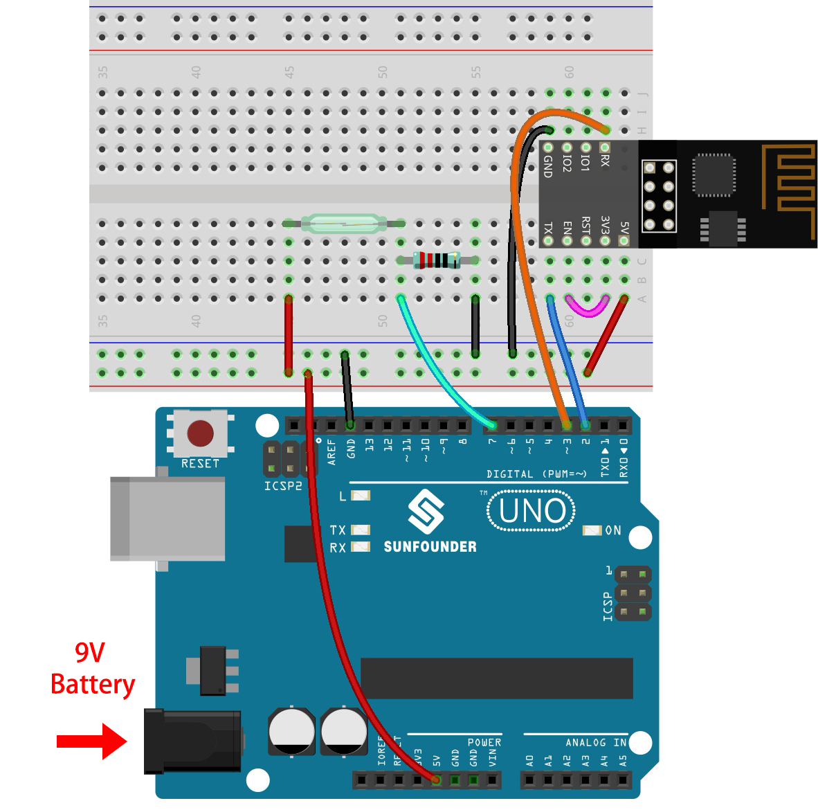
1. Build the Cirduit
Note
The ESP8266 module requires a high current to provide a stable operating environment, so make sure the 9V battery is plugged in.
2. Edit Dashboard
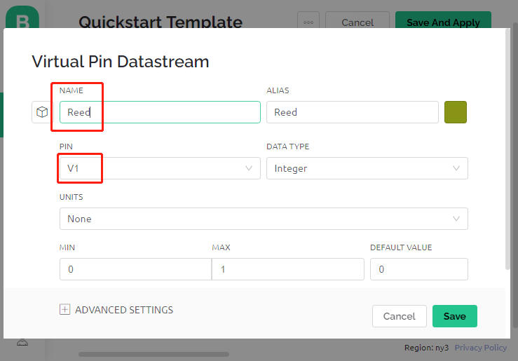
Create a Datastream of type Virtual Pin in the Datastream page to get the value of Reed Switch. Set the DATA TYPE to Integer and MIN and MAX to 0 and 1.
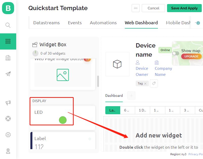
Drag and drop an LED widget on the Wed Dashboard page, at a value of 1, it will light up (with color), otherwise it will be white.
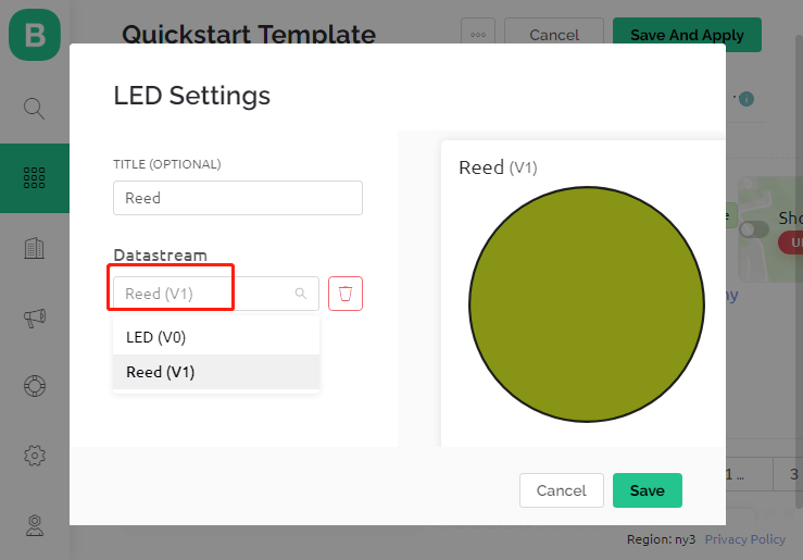
In the settings page of the LED widget, select Datastream as Reed(V1), and save it.
3. Run the Code
Open the
3.push_data_to_blynk.inofile under the path of3in1-kit\iot_project\3.push_data_to_blynk, or copy this code into Arduino IDE.Replace the
Template ID,Device Name, andAuth Tokenwith your own. You also need to enter thessidandpasswordof the WiFi you are using. For detailed tutorials, please refer to 1.4 Connecting the R3 board to Blynk.After selecting the correct board and port, click the Upoad button.
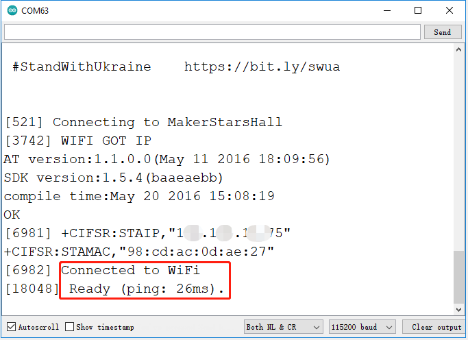
Open the Serial monitor(set baudrate to 115200) and wait for a prompt such as a successful connection to appear.
Note
If the message
ESP is not respondingappears when you connect, please follow these steps.Make sure the 9V battery is plugged in.
Reset the ESP8266 module by connecting the pin RST to GND for 1 second, then unplug it.
Press the reset button on the R3 board.
Sometimes, you may need to repeat the above operation 3-5 times, please be patient.
Now, Blynk will show the status of your doors and windows. If your doors and windows are closed, the LED widget will be green, otherwise, it will be gray.
If you want to use Blynk on mobile devices, please refer to How to use Blynk on mobile device?.
How it works?
For this example, you should focus on the following lines. “Write data every second to Blynk Cloud’s V1 Datastream” is defined by these lines.
BlynkTimer timer;

void myTimerEvent()
{
    Blynk.virtualWrite(V1, pinValue);
}

void setup()
{
    timer.setInterval(1000L, myTimerEvent);
}

void loop()
{
    timer.run(); // Initiates BlynkTimer
}
Blynk library provides a built-in timer, first we create a timer object.
BlynkTimer timer;
Set the timer interval in setup(), here we set to execute the myTimerEvent() function every 1000ms
timer.setInterval(1000L, myTimerEvent);
Run BlynkTimer in loop().
timer.run();
Edit the custom function myTimerEvent(), the code Blynk.virtualWrite(V1, pinValue) is used to write the data pinValue for V1.
void myTimerEvent()
{
    Blynk.virtualWrite(V1, pinValue);
}