Note
Hello, welcome to the SunFounder Raspberry Pi & Arduino & ESP32 Enthusiasts Community on Facebook! Dive deeper into Raspberry Pi, Arduino, and ESP32 with fellow enthusiasts.
Why Join?
Expert Support: Solve post-sale issues and technical challenges with help from our community and team.
Learn & Share: Exchange tips and tutorials to enhance your skills.
Exclusive Previews: Get early access to new product announcements and sneak peeks.
Special Discounts: Enjoy exclusive discounts on our newest products.
Festive Promotions and Giveaways: Take part in giveaways and holiday promotions.
👉 Ready to explore and create with us? Click [here] and join today!
Assemble the Car
Video
Steps
Please follow the steps below to complete the assembly of the car.
Remove the protective film on the acrylic.
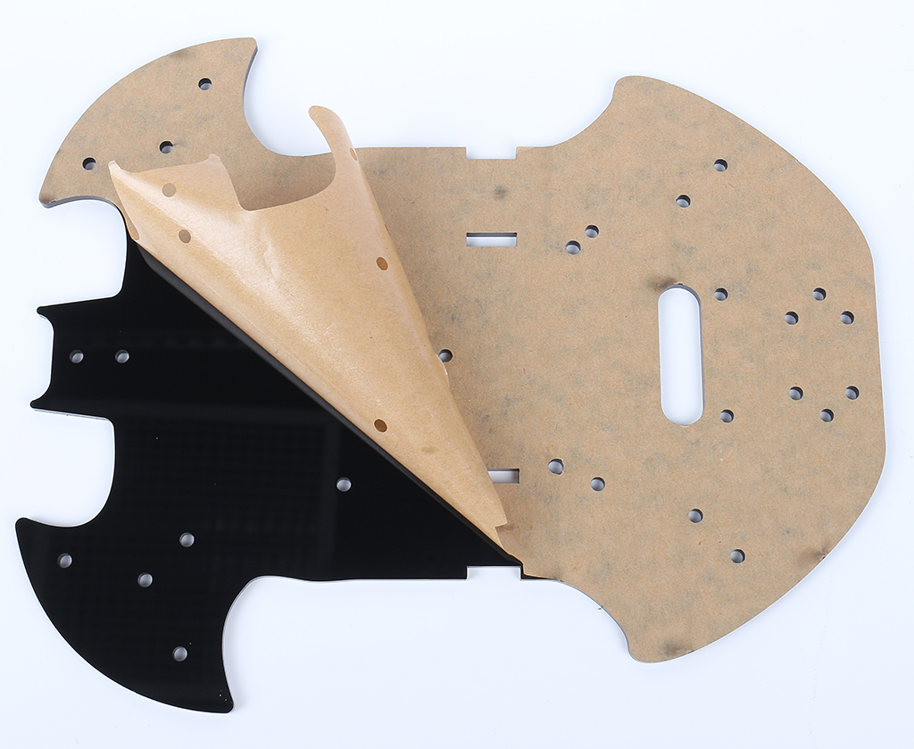
Place the board on the table as shown in the picture, the side with the same hole as the R3 board, we call A; the back is B. This will help you avoid mistakes during assembly.

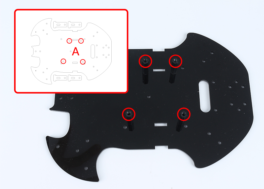
Mount the M3x24mm standoff with M3x6mm screws in the position as shown below.
Turn to the B side, use M3x30mm screws and M3 nuts to attach the TT Motor. 2 details here: 1 - the output shaft is facing the bat-shaped side; 2 - the motor cable is facing the inside.
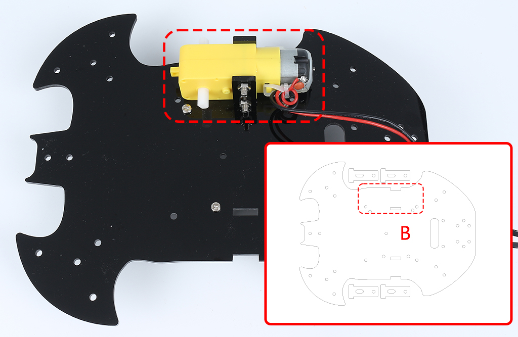
Mount another TT Motor, the same attention needs to be paid to the direction of the output shaft and the direction of the cable.

Use M3x6mm screws to mount the M3x12mm standoff in the position as shown below.

Attach the M2.5x11mm standoff to the rear of the car with M2.5x6mm screws.

Use M3x6mm screws to mount the universal wheel.

Putting on the 2 wheels and the car’s basic structure has been completed.

Attach the L9110 module with M2.5x6mm screws.

Assemble the two IR Obstacle Modules with M3x12mm screws and M3 nuts.

Turn to side B and attach the Line Track module with four M3x6mm screws and two M3x24mm standoffs.
Note
It’s advisable to first secure the M3x24mm standoffs onto the Line Track module.
One important note to keep in mind: the pins of the line sensor are slightly soft and protrude a bit towards the holes. When screwing in the M3x24mm standoffs, apply gentle pressure to push aside the sensor pins slightly.

Stick the velcro on the 9V battery and put on the battery clip. Stick the other section of the Velcro on the car to secure the battery.

Turn over to side A and mount the R3 board with M3x6mm screws.

Attach the breadboard to the front of the car. Thereafter, you will be able to add different components (e.g. ultrasonic module) to the breadboard as required for your project.

Getting the car running also requires wiring it up and writing code, which will be written in subsequent sections.