Note
Hello, welcome to the SunFounder Raspberry Pi & Arduino & ESP32 Enthusiasts Community on Facebook! Dive deeper into Raspberry Pi, Arduino, and ESP32 with fellow enthusiasts.
Why Join?
Expert Support: Solve post-sale issues and technical challenges with help from our community and team.
Learn & Share: Exchange tips and tutorials to enhance your skills.
Exclusive Previews: Get early access to new product announcements and sneak peeks.
Special Discounts: Enjoy exclusive discounts on our newest products.
Festive Promotions and Giveaways: Take part in giveaways and holiday promotions.
👉 Ready to explore and create with us? Click [here] and join today!
Stepper Motor
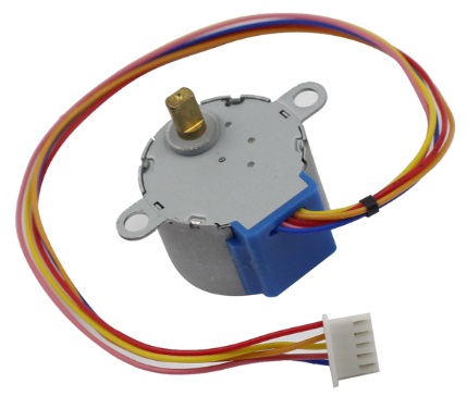
Stepper motors, due to their unique design, can be controlled to a high degree of accuracy without any feedback mechanisms. The shaft of a stepper, mounted with a series of magnets, is controlled by a series of electromagnetic coils that are charged positively and negatively in a specific sequence, precisely moving it forward or backward in small “steps”.
Principle
There are two types of steppers, unipolars and bipolars, and it is very important to know which type you are working with. In this experiment, we will use a unipolar stepper.
The stepper motor is a four-phase one, which uses a unipolarity DC power supply. As long as you electrify all phase windings of the motor by an appropriate timing sequence, you can make it rotate step by step. The schematic diagram of a four-phase reactive stepper motor:
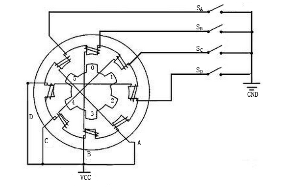
In the figure, in the middle of the motor is a rotor - a gear-shaped permanent magnet. Around the rotor, 0 to 5 are teeth. Then more outside, there are 8 magnetic poles, with each two opposite ones connected by coil winding. So they form four pairs from A to D, which is called a phase. It has four lead wires to be connected with switches SA, SB, SC, and SD. Therefore, the four phases are in parallel in the circuit, and the two magnetic poles in one phase are in series.
Here’s how a 4-phase stepper motor works:
At the beginning, switch SB is power on, switch SA, SC, and SD is power off, and B-phase magnetic poles align with tooth 0 and 3 of the rotor. At the same time, tooth 1 and 4 generate staggered teeth with C- and D-phase poles. Tooth 2 and 5 generate staggered teeth with D- and A-phase poles. When switch SC is power on, switch SB, SA, and SD is power off, the rotor rotates under magnetic field of C-phase winding and that between tooth 1 and 4. Then tooth 1 and 4 align with the magnetic poles of C-phase winding. While tooth 0 and 3 generate staggered teeth with A- and B-phase poles, and tooth 2 and 5 generate staggered teeth with the magnetic poles of A- and D-phase poles. The similar situation goes on and on. Energize the A, B, C and D phases in turn, and the rotor will rotate in the order of A, B, C and D.
The four-phase stepper motor has three operating modes: single four-step, double four-step, and eight-step. The step angle for the single four-step and double four-step are the same, but the driving torque for the single four-step is smaller. The step angle of the eight-step is half that of the single four-step and double four-step. Thus, the eight-step operating mode can keep high driving torque and improve control accuracy. In this experiment, we let the stepper motor work in the eight-step mode.
ULN2003 Module
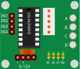
To apply the motor in the circuit, a driver board needs to be used. Stepper Motor Driver-ULN2003 is a 7-channel inverter circuit. That is, when the input end is at high level, the output end of ULN2003 is at low level, and vice versa. If we supply high level to IN1, and low level to IN2, IN3 and IN4, then the output end OUT1 is at low level, and all the other output ends are at high level. So D1 lights up, switch SA is power on, and the stepper motor rotates one step. The similar case repeats on and on. Therefore, just give the stepper motor a specific timing sequence, it will rotate step by step. The ULN2003 here is used to provide particular timing sequences for the stepper motor.
Example
Lesson 19 Stepper Motor (Mega Board Project)
Lesson 19 Stepper Motor (R3 Board Project)