Note
Hello, welcome to the SunFounder Raspberry Pi & Arduino & ESP32 Enthusiasts Community on Facebook! Dive deeper into Raspberry Pi, Arduino, and ESP32 with fellow enthusiasts.
Why Join?
Expert Support: Solve post-sale issues and technical challenges with help from our community and team.
Learn & Share: Exchange tips and tutorials to enhance your skills.
Exclusive Previews: Get early access to new product announcements and sneak peeks.
Special Discounts: Enjoy exclusive discounts on our newest products.
Festive Promotions and Giveaways: Take part in giveaways and holiday promotions.
👉 Ready to explore and create with us? Click [here] and join today!
2.1.7 Potentionmeter
Note

Depending on your kit version, please identify whether you have ADC0834 or MCP3008 and proceed with the matching section.
Introduction
The ADC function can be used to convert analog signals to digital signals, and in this experiment, ADC0834 is used to get the function involving ADC. Here, we implement this process by using potentiometer. Potentiometer changes the physical quantity – voltage, which is converted by the ADC function.
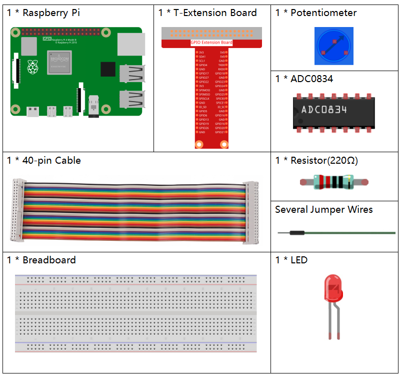
Required Components
In this project, we need the following components.
It’s definitely convenient to buy a whole kit, here’s the link:
Name |
ITEMS IN THIS KIT |
LINK |
|---|---|---|
Raphael Kit |
337 |
You can also buy them separately from the links below.
COMPONENT INTRODUCTION |
PURCHASE LINK |
|---|---|
- |
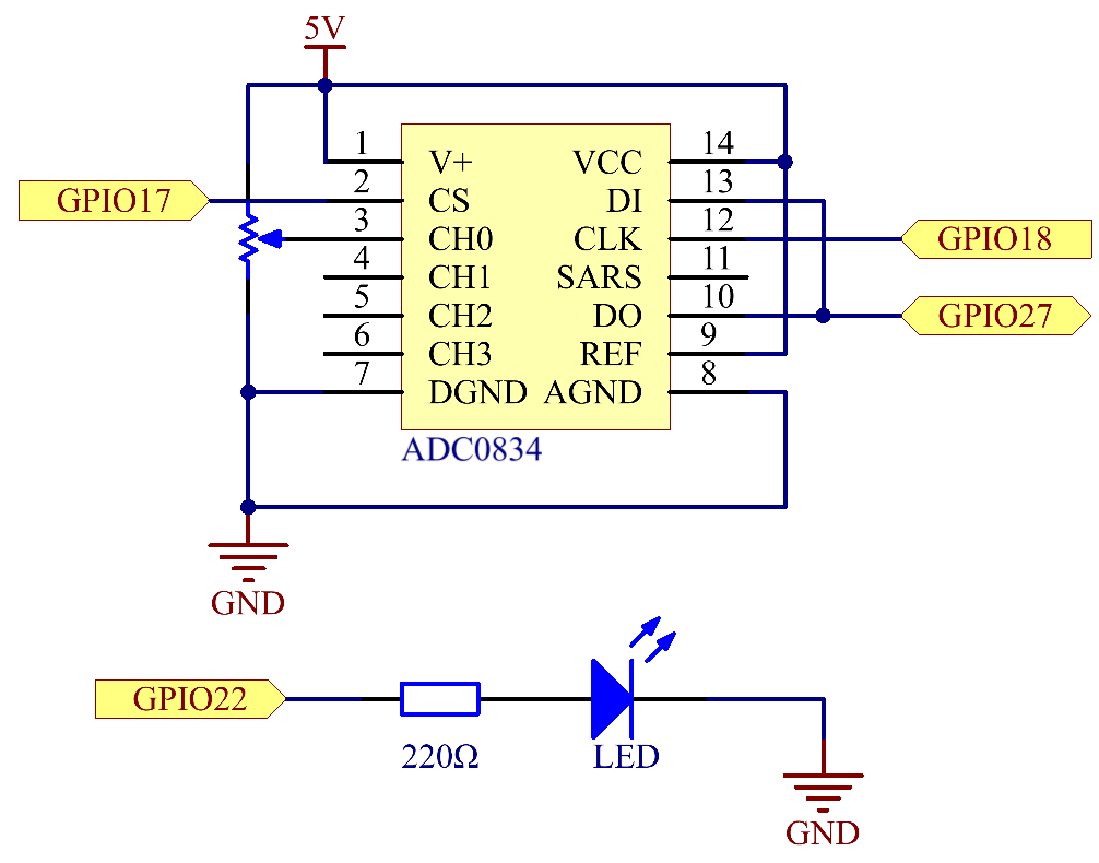
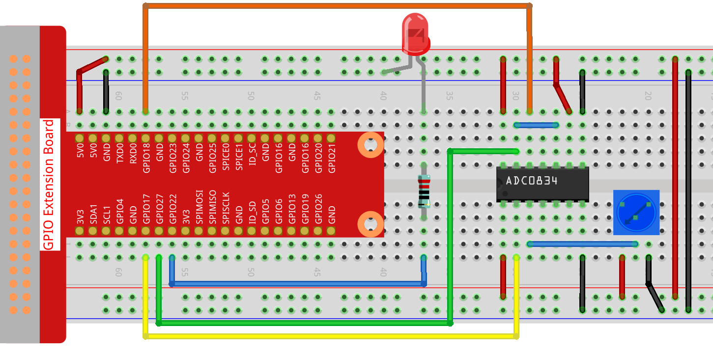
Schematic Diagram
Experimental Procedures
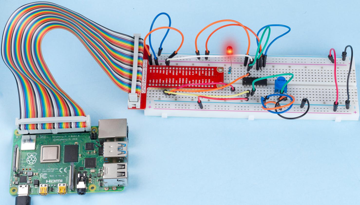
Step 1: Build the circuit.
Note
Please place the chip by referring to the corresponding position depicted in the picture. Note that the grooves on the chip should be on the left when it is placed.
Step 2: Go to the folder of the code.
cd ~/raphael-kit/nodejs/
Step 3: Run the code.
sudo node potentionmeter.js
After the code runs, rotate the knob on the potentiometer, the intensity of LED will change accordingly.
Code
const Gpio = require('pigpio').Gpio;
const ADC0834 = require('./adc0834.js').ADC0834;

const adc = new ADC0834(17, 18, 27);
const led = new Gpio(22, {mode: Gpio.OUTPUT});

setInterval(() => {
    adc.read(0).then((value) => {
        console.log(`Current analogVal: ${value}\n`);
        led.pwmWrite(value);
    }, (error)=>{
        console.log("Error: " + error);
    });
}, 100);
Code Explanation
const Gpio = require('pigpio').Gpio;
Import the pigpio module.
const ADC0834 = require('./adc0834.js').ADC0834;
We import an ADC0834 constructor to use the adc0834 module.
const adc = new ADC0834(17, 18, 27);
Instantiate an ADC0834 object, the three parameters are its three pins.
This is a promise object, you may need to understand the concept from the following link.
setInterval(() => {
    adc.read(0).then((value) => {
        console.log(`Current analogVal: ${value}\n`);
        led.pwmWrite(value);
    }, (error)=>{
        console.log("Error: " + error);
    });
}, 100);
The value of ADC0834 channel 0 (channel 0 is connected to the potentiometer) is read every 100ms, and the value will be stored in value.
Print value and use it to control the brightness of the LED, now you can see that the brightness of the LED changes with the value of the potentiometer.
Phenomenon Picture