Note
Hello, welcome to the SunFounder Raspberry Pi & Arduino & ESP32 Enthusiasts Community on Facebook! Dive deeper into Raspberry Pi, Arduino, and ESP32 with fellow enthusiasts.
Why Join?
Expert Support: Solve post-sale issues and technical challenges with help from our community and team.
Learn & Share: Exchange tips and tutorials to enhance your skills.
Exclusive Previews: Get early access to new product announcements and sneak peeks.
Special Discounts: Enjoy exclusive discounts on our newest products.
Festive Promotions and Giveaways: Take part in giveaways and holiday promotions.
👉 Ready to explore and create with us? Click [here] and join today!
1.3.3 Relay
Introduction
In this project, we will learn to use a relay. It is one of the commonly used components in automatic control system. When the voltage, current, temperature, pressure, etc., reaches, exceeds or is lower than the predetermined value, the relay will connect or interrupt the circuit, to control and protect the equipment.
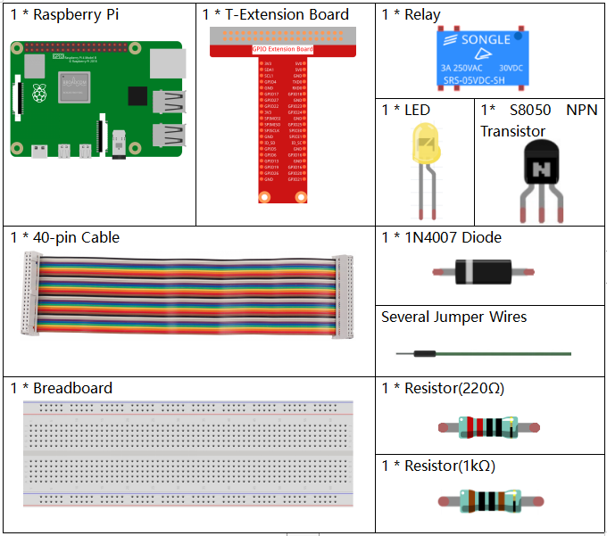
Required Components
In this project, we need the following components.
It’s definitely convenient to buy a whole kit, here’s the link:
Name |
ITEMS IN THIS KIT |
LINK |
|---|---|---|
Raphael Kit |
337 |
You can also buy them separately from the links below.
COMPONENT INTRODUCTION |
PURCHASE LINK |
|---|---|
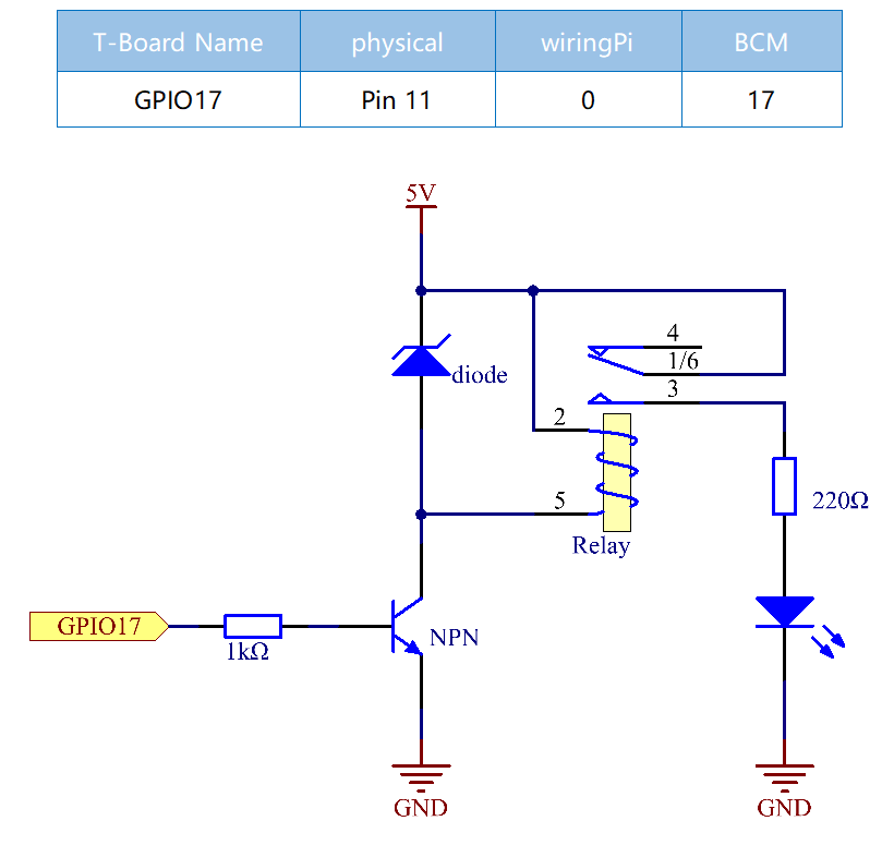
Schematic Diagram
Experimental Procedures
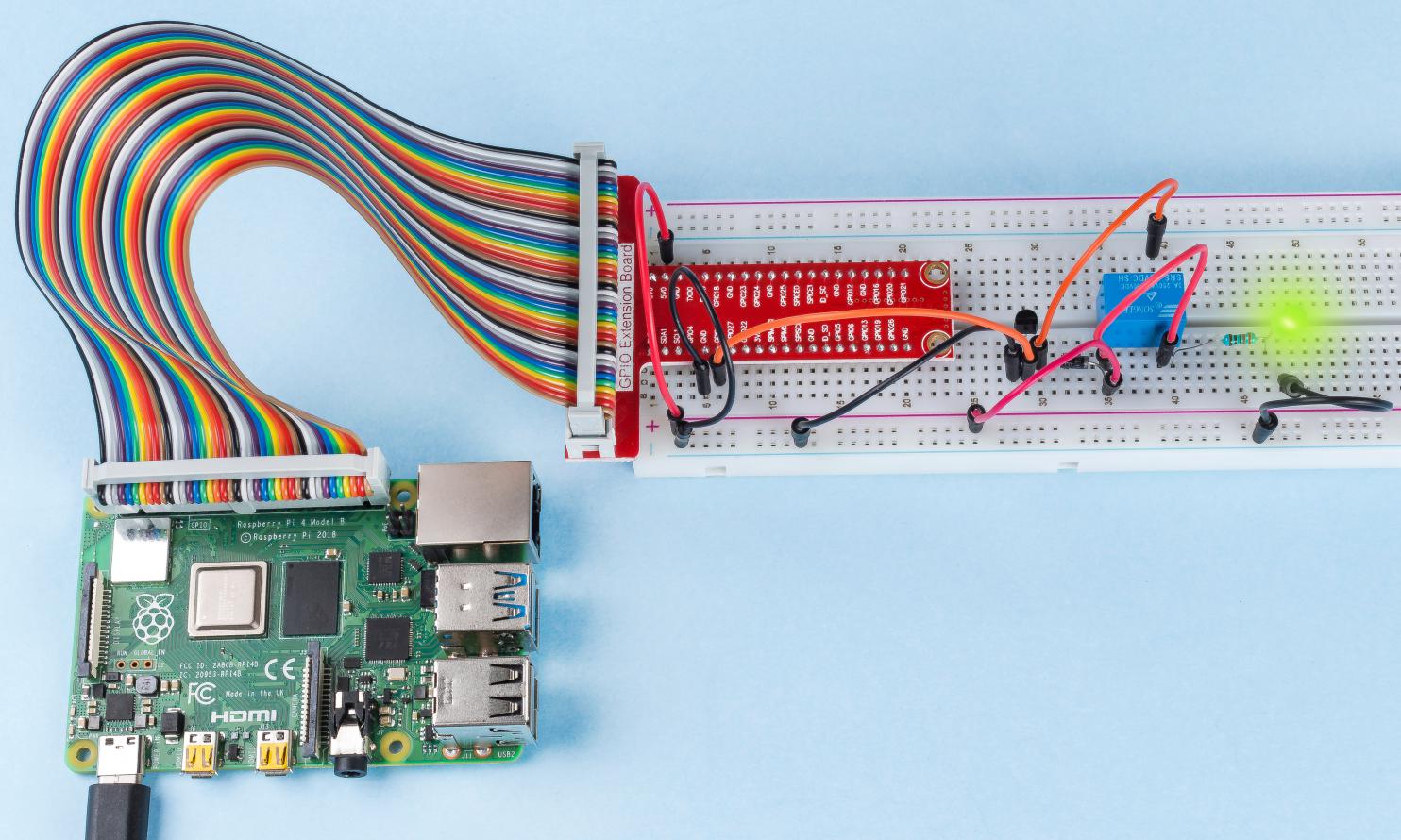
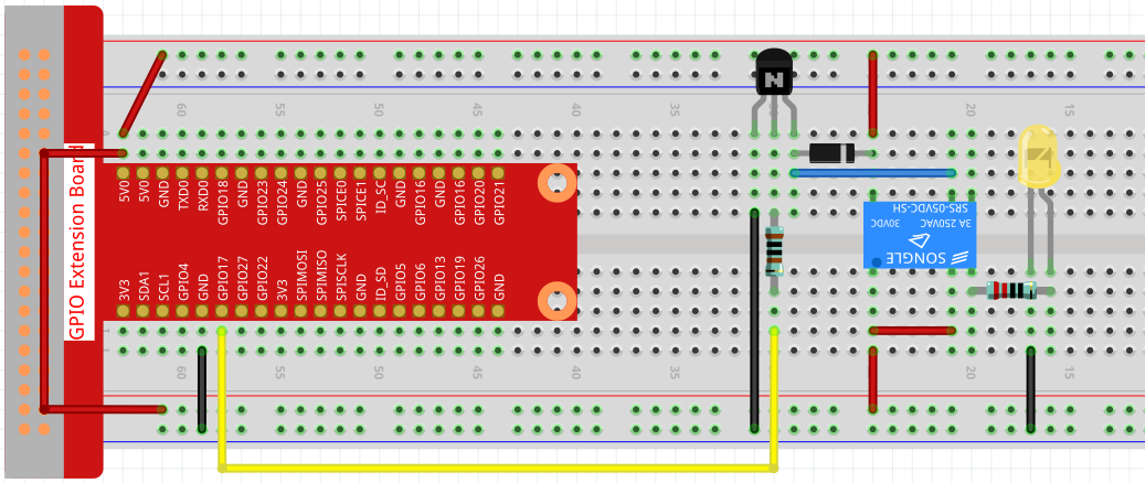
Step 1: Build the circuit.
Step 2: Open the code file.
cd ~/raphael-kit/c/1.3.3
Step 3: Compile the code.
gcc 1.3.3_Relay.c -lwiringPi
Step 4: Run the executable file.
sudo ./a.out
After the code runs, the LED will light up. In addition, you can hear a ticktock caused by breaking normally close contact and closing normally open contact.
Note
If it does not work after running, or there is an error prompt: "wiringPi.h: No such file or directory", please refer to Install and Check the WiringPi.
Code
#include <wiringPi.h>
#include <stdio.h>
#define RelayPin 0

int main(void){
    if(wiringPiSetup() == -1){ //when initialize wiring failed, print message to screen
        printf("setup wiringPi failed !");
        return 1;
    }
    pinMode(RelayPin, OUTPUT);   //set GPIO17(GPIO0) output
    while(1){
        // Tick
        printf("Relay Open......\n");
        digitalWrite(RelayPin, LOW);
        delay(1000);
        // Tock
        printf("......Relay Close\n");
        digitalWrite(RelayPin, HIGH);
        delay(1000);
    }

    return 0;
}
Code Explanation
digitalWrite(RelayPin, LOW);
Set the I/O port as low level (0V), thus the transistor is not energized and the coil is not powered. There is no electromagnetic force, so the relay opens, LED does not turn on.
digitalWrite(RelayPin, HIGH);
set the I/O port as high level (5V) to energize the transistor. The coil of the relay is powered and generate electromagnetic force, and the relay closes, LED lights up.
Phenomenon Picture