注釈
こんにちは!SunFounder Raspberry Pi & Arduino & ESP32 Enthusiasts Communityへようこそ!Facebookで仲間と一緒にRaspberry Pi、Arduino、ESP32をさらに深く探求しましょう。
参加する理由
エキスパートサポート: コミュニティやチームの助けを借りて、購入後の問題や技術的な課題を解決しましょう。
学び&共有: スキルを向上させるためのヒントやチュートリアルを交換しましょう。
独占プレビュー: 新製品発表や先行プレビューをいち早く入手できます。
特別割引: 新製品に対する独占的な割引を楽しめます。
お祭りプロモーションとプレゼント: プレゼントや休日のプロモーションに参加しましょう。
👉 一緒に探求して創造する準備はできましたか?[ここ]をクリックして、今すぐ参加しましょう!
30. Arduino レーダーシステム
この魅力的なレッスンでは、サーボと超音波モジュールを組み合わせたダイナミックなArduinoレーダーシステムを構築し、Processing PDEで作成したアニメーションインターフェースに、近くの物体の位置を検出して表示します。
このレッスンの終了時には、以下のことができるようになります:
サーボと超音波モジュールを使用してスキャンレーダーを構築する。
Arduino IDEからProcessing PDEへシリアル通信を介してデータを送信する。
シンプルなアニメーションを作成し、データを効果的に視覚化するためのツールであるProcessing PDEの基本を探求する。
Processing PDEを使用してリアルタイムデータを視覚化するスキルを身につけ、データフローやセンサーのダイナミクスに対する理解を深める。
1. 必要なコンポーネント
1 * Arduino Uno R3 |
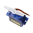
1 * サーボ |
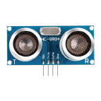
1 * 超音波モジュール |
|
|
|
|
|
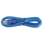
1 * USBケーブル |
1 * ブレッドボード |
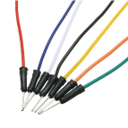
ジャンパーワイヤー |
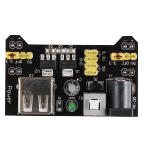
1 * ブレッドボード電源モジュール |
|
|
|
|
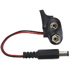
1 * 9Vバッテリー |
1 * バッテリーケーブル |
||
|
|


2. サーボの準備
1. 回路の構築
それでは、回路の構築を始めましょう。
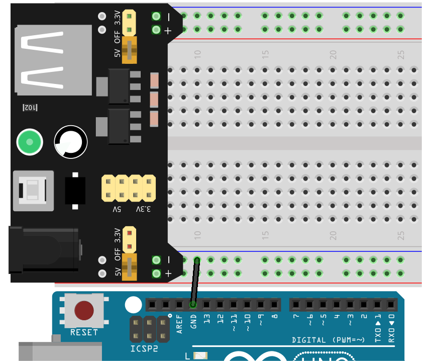
まず、ブレッドボードに電源モジュールを挿入し、ジャンパーワイヤーを使用してブレッドボードの負極とArduino Uno R3のGNDを接続し、共通のグランドを確立します。
注釈
配線図におけるブレッドボード上の正極と負極の順序は、キットに含まれているブレッドボードのものとは逆になっています。
実際の配線では、ブレッドボード電源モジュールを番号の高い側(60~65)から挿入し、電源モジュールの「-」がブレッドボードの負極「-」に、「+」が正極「+」に入るようにします。
3本の短いジャンパーワイヤーを使用して、サーボの3本のワイヤーを延長します。黄色のワイヤーをArduino Uno R3のピン12に、赤いワイヤーをブレッドボードの正極に、茶色のワイヤーをブレッドボードの負極に接続します。

2. コードの作成
Arduinoレーダーシステムでは、サーボが0度から180度まで往復するように動作します。まず、初期角度を90度に設定する必要があります。
Arduino IDEを開き、「ファイル」メニューから「新しいスケッチ」を選択して新しいプロジェクトを開始します。
スケッチを
Lesson30_Servo_Angleとして保存します(Ctrl + Sまたは「保存」をクリック)。サーボを動作させるのは非常に簡単です。
Servoライブラリをコードに含め、次にServoオブジェクトを作成し、指定されたピンにサーボオブジェクトをアタッチします。その後、write()関数を使用してサーボを特定の角度に設定できます。以下にその方法を示します。
#include <Servo.h>

Servo myServo;  // Create a Servo object

const int servoPin = 12;  // servo connected to digital pin 12

void setup() {
  myServo.attach(servoPin);  // Attach the Servo object to the specified pin
  myServo.write(90);         // Initial position set to 90 degrees
}

void loop() {
  // put your main code here, to run repeatedly:
}
次に、コードをArduinoボードにアップロードします。サーボが90度の位置に移動したことを示す音が聞こえるでしょう。
その後、指定された角度でサーボに一方のサーボアームを取り付けます。サーボアームをサーボ本体に平行に保つようにし、わずかな傾きは性能に影響を与えません。

3. 超音波モジュールの準備
1. 回路の構築
超音波モジュールをサーボに取り付けるためのマウントを見つけるか、手動で作成してください。
注釈
このキットにはマウントが含まれていないため、自分で購入するか作成する必要があります。
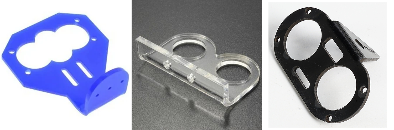
次に、通常はM2x4のネジとM2ナットを使用して、超音波モジュールをマウントに固定します。
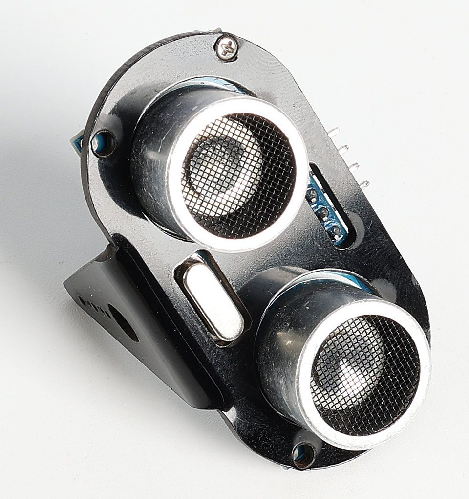
超音波モジュールを取り付けたマウントをサーボアームに固定します。Arduinoボードに電源を入れたときに、超音波モジュールが前方を向くようにしてください。

次に、ジャンパーワイヤーを使用して超音波モジュールを接続します:VCCをブレッドボードの正極に、TrigピンをArduinoボードのピン10に、Echoピンをピン11に、GNDをブレッドボードの負極に接続します。

2. コードの作成
以前保存したスケッチ
Lesson30_Sero_Angleを開きます。「ファイル」メニューから「名前を付けて保存」を選択し、Lesson30_Arduino_Radarとして保存します。「保存」をクリックしてください。次に、超音波モジュールのピンを定義し、それぞれのモードを
OUTPUTとINPUTに設定します。このコードでは、Processing PDEとの通信にシリアルモニタを使用する必要があるため、9600bpsでシリアル通信を開始します。
#include <Servo.h>

Servo myServo;  // Create a Servo object

const int servoPin = 12;  // servo connected to digital pin 12

#define TRIGGER_PIN 10  // Pin to trigger the ultrasonic pulse
#define ECHO_PIN 11     // Pin to receive the echo

void setup() {
  pinMode(TRIGGER_PIN, OUTPUT);  // Set the Trig pin as output
  pinMode(ECHO_PIN, INPUT);      // Set the Echo pin as input
  Serial.begin(9600);            // Start serial communication for debugging
  myServo.attach(servoPin);      // Defines on which pin is the servo attached
  myServo.write(90);             // Initial position set to 90 degrees
}
超音波モジュールで計測された距離を取得するための特定の関数が必要になります。この関数がどのように実装されているかは、コード作成 - 距離の読み取り を参照してください。
void loop() {
  // put your main code here, to run repeatedly:

}

// Function to read the sensor data and calculate the distance
long measureDistance() {
  digitalWrite(TRIGGER_PIN, LOW);  // Ensure Trig pin is low before a pulse
  delayMicroseconds(2);
  digitalWrite(TRIGGER_PIN, HIGH);  // Send a high pulse
  delayMicroseconds(10);            // Pulse duration of 10 microseconds
  digitalWrite(TRIGGER_PIN, LOW);   // End the high pulse

  long duration = pulseIn(ECHO_PIN, HIGH);  // Measure the duration of high level on Echo pin
  long distance = duration * 0.034 / 2;     // Calculate the distance (in cm)
  return distance;
}
forループを使用して、サーボの回転角度を15度から165度の間に制限します。この範囲はセットアップに応じて調整できます。サーボは0度から180度まで回転できます。
void loop() {
  // rotates the servo from 15 to 165 degrees
  for (int i = 15; i <= 165; i++) {
    myServo.write(i);
    delay(30);
  }
}
サーボが回転する際に、超音波センサーが周囲の物体までの距離を検出し、その読み取り値をシリアルモニタに表示します。これらのデータはシリアルポートを介してProcessing PDEに送信されます。
注釈
次の
Serial.print()関数の4行は変更しないでください。シリアルモニタに表示されるデータは、指定された形式でProcessing PDEに送信する必要があります。Processingコードでは、文字
,がサーボ角度を決定し、指定された変数に格納されます。Processingコードでは、文字
.が検出された距離を決定し、指定された変数に格納されます。
void loop() {
  // rotates the servo from 15 to 165 degrees
  for (int i = 15; i <= 165; i++) {
    myServo.write(i);
    delay(30);
    long distance = measureDistance();  // Call the function to measure distance
    Serial.print(i);                    // Sends the current degree into the Serial Port
    Serial.print(",");                  // Sends addition character right next to the previous value needed later in the Processing PDE for indexing
    Serial.print(distance);             // Sends the distance value into the Serial Port
    Serial.print(".");                  // Sends addition character right next to the previous value needed later in the Processing PDE for indexing
  }
}
サーボを165度から15度に戻し、角度と距離の値をシリアルポートに前と同様に出力します。これらのデータはシリアルポートを通じてProcessing PDEに送信されます。
void loop() {
  // rotates the servo from 15 to 165 degrees
  for (int i = 15; i <= 165; i++) {
    myServo.write(i);
    delay(30);
    long distance = measureDistance();  // Call the function to measure distance
    Serial.print(i);                    // Sends the current degree into the Serial Port
    Serial.print(",");                  // Sends addition character right next to the previous value needed later in the Processing PDE for indexing
    Serial.print(distance);             // Sends the distance value into the Serial Port
    Serial.print(".");                  // Sends addition character right next to the previous value needed later in the Processing PDE for indexing
  }
  // rotates the servo from 165 to 15 degrees
  for (int i = 165; i > 15; i--) {
    myServo.write(i);
    delay(30);
    long distance = measureDistance();  // Call the function to measure distance
    Serial.print(i);                    // Sends the current degree into the Serial Port
    Serial.print(",");                  // Sends addition character right next to the previous value needed later in the Processing PDE for indexing
    Serial.print(distance);             // Sends the distance value into the Serial Port
    Serial.print(".");                  // Sends addition character right next to the previous value needed later in the Processing PDE for indexing
  }
}
完成したコードは以下の通りです。Arduinoボードにアップロードし、サーボが超音波モジュールと共に左右に動き続ける様子を確認できます。データはシリアルモニタに一行形式で出力されます。
#include <Servo.h>

Servo myServo;  // Create a Servo object

const int servoPin = 12;  // servo connected to digital pin 12

#define TRIGGER_PIN 10  // Pin to trigger the ultrasonic pulse
#define ECHO_PIN 11     // Pin to receive the echo

void setup() {
  pinMode(TRIGGER_PIN, OUTPUT);  // Set the Trig pin as output
  pinMode(ECHO_PIN, INPUT);      // Set the Echo pin as input
  Serial.begin(9600);            // Start serial communication for debugging
  myServo.attach(servoPin);      // Defines on which pin is the servo attached
  myServo.write(90);             // Initial position set to 90 degrees
}

void loop() {
  // rotates the servo from 15 to 165 degrees
  for (int i = 15; i <= 165; i++) {
    myServo.write(i);
    delay(30);
    long distance = measureDistance();  // Call the function to measure distance
    Serial.print(i);                    // Sends the current degree into the Serial Port
    Serial.print(",");                  // Sends addition character right next to the previous value needed later in the Processing PDE for indexing
    Serial.print(distance);             // Sends the distance value into the Serial Port
    Serial.print(".");                  // Sends addition character right next to the previous value needed later in the Processing PDE for indexing
  }
  // Repeats the previous lines from 165 to 15 degrees
  for (int i = 165; i > 15; i--) {
    myServo.write(i);
    delay(30);
    long distance = measureDistance();  // Call the function to measure distance
    Serial.print(i);                    // Sends the current degree into the Serial Port
    Serial.print(",");                  // Sends addition character right next to the previous value needed later in the Processing PDE for indexing
    Serial.print(distance);             // Sends the distance value into the Serial Port
    Serial.print(".");                  // Sends addition character right next to the previous value needed later in the Processing PDE for indexing
  }
}

// Function to read the sensor data and calculate the distance
long measureDistance() {
  digitalWrite(TRIGGER_PIN, LOW);  // Ensure Trig pin is low before a pulse
  delayMicroseconds(2);
  digitalWrite(TRIGGER_PIN, HIGH);  // Send a high pulse
  delayMicroseconds(10);            // Pulse duration of 10 microseconds
  digitalWrite(TRIGGER_PIN, LOW);   // End the high pulse

  long duration = pulseIn(ECHO_PIN, HIGH);  // Measure the duration of high level on Echo pin
  long distance = duration * 0.034 / 2;     // Calculate the distance (in cm)
  return distance;
}
最後に、コードを保存して作業スペースを整理することを忘れないでください。
Question
上記のコードでは、超音波モジュールは毎度1度ごとに読み取りを行っています。もし読み取り頻度が高すぎると感じ、5度ごとに読み取りを行いたい場合、コードをどのように変更すれば良いでしょうか?
4. Processing PDEの準備
サーボと超音波モジュールの準備が整ったら、次にProcessing PDEを使用して、レーダーの回転角度と検出対象を表示するレーダーインターフェイスを生成するためのコードを作成および実行します。
1. Processing PDEのダウンロードとインストール
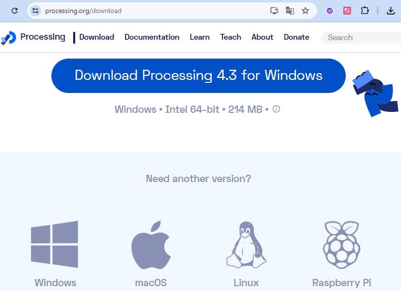
Processingの公式ダウンロードページにアクセスします:ダウンロード Processing 。
お使いのオペレーティングシステムに応じたダウンロードを選択します。
各マシンでのインストールは簡単です。
Windowsの場合、
.zipファイルがあります。ダブルクリックして、その中のフォルダをハードディスク上の任意の場所にドラッグします。Program Filesやデスクトップでも構いませんが、重要なのはそのフォルダを.zipファイルから取り出すことです。その後、processing.exeをダブルクリックして起動します。Mac OS Xバージョンも
.zipファイルです。ダブルクリックして Processing アイコンを Applications フォルダにドラッグします。別のユーザーのマシンを使用していて Applications フォルダを変更できない場合は、アプリケーションをデスクトップにドラッグしてください。その後、 Processing アイコンをダブルクリックして起動します。Linuxバージョンは
.tar.gzファイルで、多くのLinuxユーザーにはおなじみの形式です。ホームディレクトリにファイルをダウンロードし、ターミナルウィンドウを開いて次のコマンドを入力します:
tar xvfz processing-xxxx.tgz
(xxxxはファイル名の残り、つまりバージョン番号に置き換えてください。)これにより、processing-2.0などの名前のフォルダが作成されます。そのディレクトリに移動します:
cd processing-xxxx
そして実行します:
./processing
問題がなければ、メインのProcessingウィンドウが表示されるはずです。
2. コードの修正と実行
Processing PDEで実行する必要があるコードをダウンロードして解凍します。
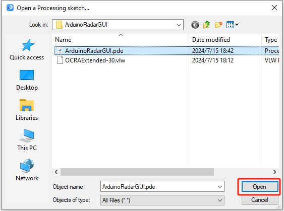
File -> Open をクリックします。
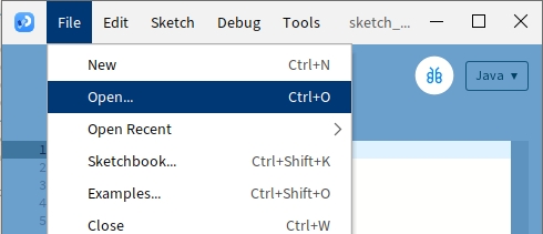
解凍したフォルダに移動し、 ArduinoRadarGUI.pde を選択して、 Open をクリックします。
次に、コード内のシリアルポートをArduino IDEで設定したものに変更する必要があります。
void setup() {
  //fullScreen(); // comment out this line if you do not want full-screen display.
  size (1680, 945); // ***CHANGE THIS TO YOUR SCREEN RESOLUTION***

  smooth();
  myPort = new Serial(this, "COM39", 9600); // starts the serial communication
  myPort.bufferUntil('.'); // reads the data from the serial port up to the character '.'. So actually it reads this: angle,distance.
  orcFont = loadFont("OCRAExtended-30.vlw");
}
シリアルポートを変更したら、コードを実行します。コードを実行する前に、Arduino Uno R3がコンピュータに接続されており、ポートが設定したものと一致していることを確認してください。

サーボが左右にスキャンし、超音波モジュールで検出された物体の角度がProcessingインターフェースに表示され、40cm以内の物体を表示する様子が確認できます。
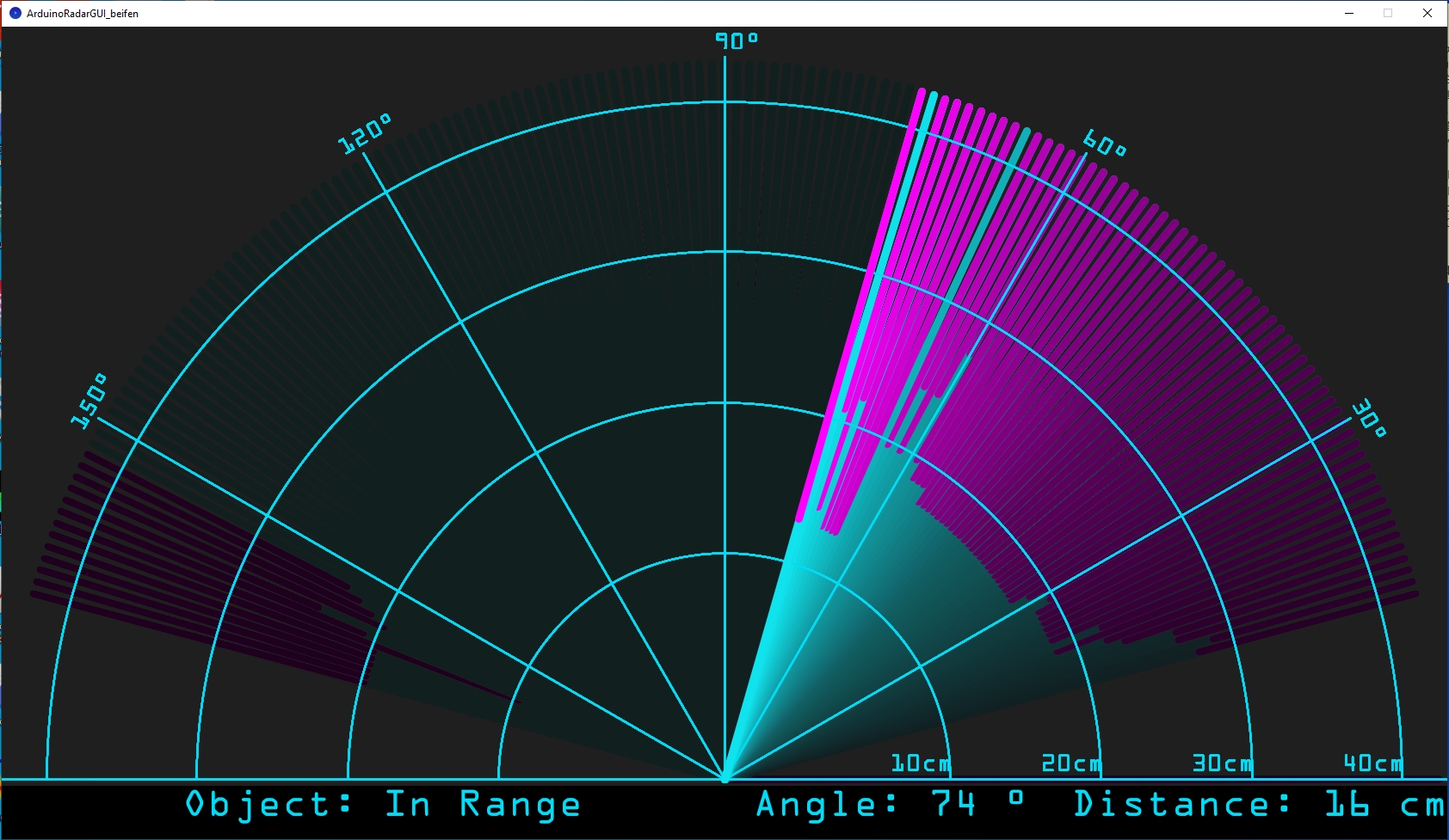
表示が完全に見えない場合は、画面に合わせて解像度を調整できます。画面比率は16:9にするのが理想です。また、
fullScreen();のコメントを解除すると、Processingの表示がフルスクリーンになります。終了するにはESCキーを押してください。
注釈
インターフェース全体をお好みに合わせて調整することも可能です。コード内の関数の詳細については、次のリンク先を参照してください: Processing Reference 。
void setup() {

  //fullScreen(); // comment out this line if you do not want full-screen display.
  size (1680, 945); // ***CHANGE THIS TO YOUR SCREEN RESOLUTION***

  smooth();
  myPort = new Serial(this, "COM39", 9600); // starts the serial communication
  myPort.bufferUntil('.'); // reads the data from the serial port up to the character '.'. So actually it reads this: angle,distance.
  orcFont = loadFont("OCRAExtended-30.vlw");
}
最後に、コードを保存し、作業スペースを整理することを忘れないでください。
Summary
このレッスンでは、サーボと超音波モジュールを使用してArduinoレーダーシステムを構築し、0度から180度までスキャンするシステムを作成しました。その後、Processing PDEで作成したアニメーションインターフェースに、検出された物体とその対応する角度を表示させ、実際のレーダーシステムをシミュレートしました。
Arduino IDEからProcessing PDEにシリアル通信を通じてデータを送信する方法を学び、2つのプログラミングプラットフォーム間でのデータ交換を実現しました。また、Processingの基本的な環境も探求し、シンプルなアニメーションを作成し、データを効果的に視覚化するためのツールとして利用できることを学びました。
ProcessingはJavaをベースにしており、非常にシンプルで使いやすいプログラミング要素が揃っているため、初心者でも簡単に扱えます。これからもProcessingを使ってクリエイティブで視覚的なプロジェクトに挑戦し、その可能性を最大限に活用してみてください。さらなる洞察とチュートリアルについては、「Getting Started with Processing」チュートリアルをご覧ください。