Note
Hello, welcome to the SunFounder Raspberry Pi & Arduino & ESP32 Enthusiasts Community on Facebook! Dive deeper into Raspberry Pi, Arduino, and ESP32 with fellow enthusiasts.
Why Join?
Expert Support: Solve post-sale issues and technical challenges with help from our community and team.
Learn & Share: Exchange tips and tutorials to enhance your skills.
Exclusive Previews: Get early access to new product announcements and sneak peeks.
Special Discounts: Enjoy exclusive discounts on our newest products.
Festive Promotions and Giveaways: Take part in giveaways and holiday promotions.
👉 Ready to explore and create with us? Click [here] and join today!
1.2.1 Active Buzzer
Introduction
In this project, we will learn how to drive an active buzzer to beep with a NPN transistor.
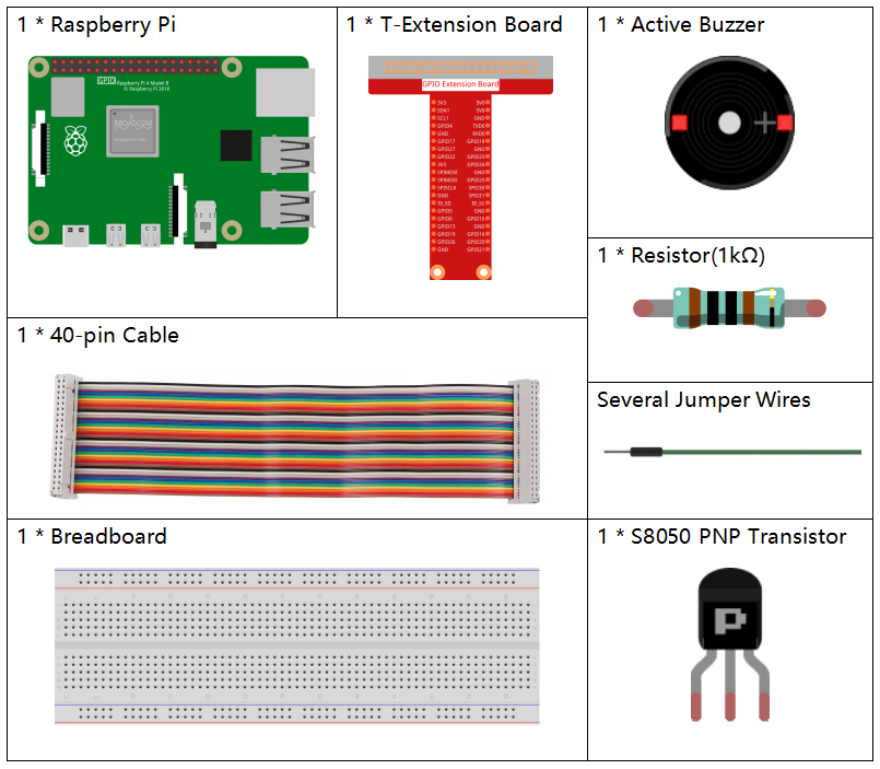
Required Components
In this project, we need the following components.
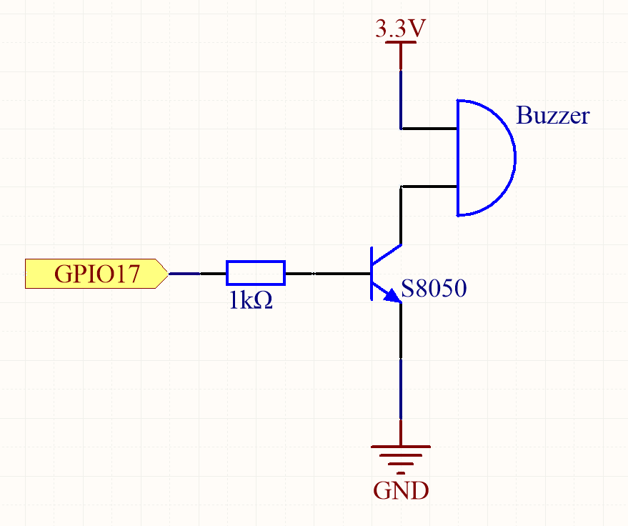
Schematic Diagram
In this experiment, an active buzzer, an NPN transistor, and a 1kΩ resistor are used. The resistor is connected between the GPIO pin and the transistor’s base to limit the base current and protect the transistor. When GPIO17 on the Raspberry Pi outputs a high level (3.3V), the transistor enters saturation mode, allowing current to flow through the buzzer, which then sounds. When the GPIO17 outputs a low level (0V), the transistor is turned off, and the buzzer remains silent.
T-Board Name |
physical |
wiringPi |
BCM |
GPIO17 |
Pin 11 |
0 |
17 |
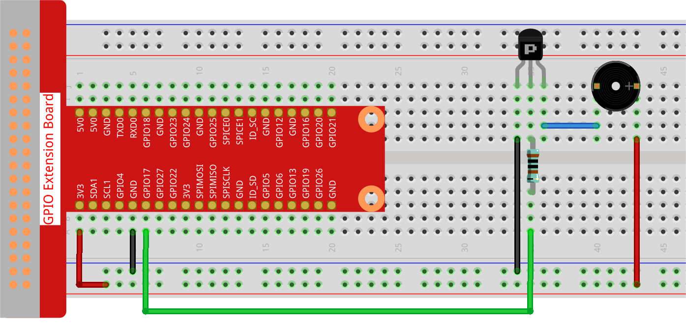
Experimental Procedures
Step 1: Build the circuit. (The active buzzer has a white table sticker on the surface and a black back.)
Step 2: Open the code file.
cd ~/davinci-kit-for-raspberry-pi/python-pi5
Step 3: Run.
sudo python3 1.2.1_ActiveBuzzer.py
The code run, the buzzer beeps.
Warning
If there is an error prompt RuntimeError: Cannot determine SOC peripheral base address, please refer to If gpiozero doesn’t work.
Code
Note
You can Modify/Reset/Copy/Run/Stop the code below. But before that, you need to go to source code path like davinci-kit-for-raspberry-pi/python-pi5. After modifying the code, you can run it directly to see the effect.
#!/usr/bin/env python3
from gpiozero import Buzzer
from time import sleep

# Initialize a Buzzer object on GPIO pin 17
buzzer = Buzzer(17)

try:
    while True:
        # Turn on the buzzer
        print('Buzzer On')
        buzzer.on()
        sleep(0.1)  # Keep the buzzer on for 0.1 seconds

        # Turn off the buzzer
        print('Buzzer Off')
        buzzer.off()
        sleep(0.1)  # Keep the buzzer off for 0.1 seconds

except KeyboardInterrupt:
    # Handle KeyboardInterrupt (Ctrl+C) for clean script termination
    pass
Code Explanation
These statements import the
Buzzerclass from thegpiozerolibrary and thesleepfunction from thetimemodule.#!/usr/bin/env python3 from gpiozero import Buzzer from time import sleep
This line creates a
Buzzerobject connected to GPIO pin 17 on the Raspberry Pi.# Initialize a Buzzer object on GPIO pin 17 buzzer = Buzzer(17)
In an infinite loop (
while True), the buzzer is turned on and off every 0.1 seconds.printstatements provide a console output for each action.try: while True: # Turn on the buzzer print('Buzzer On') buzzer.on() sleep(0.1) # Keep the buzzer on for 0.1 seconds # Turn off the buzzer print('Buzzer Off') buzzer.off() sleep(0.1) # Keep the buzzer off for 0.1 seconds
This segment ensures the program can be terminated safely using a keyboard interrupt (Ctrl+C) without throwing an error.
except KeyboardInterrupt:
# Handle KeyboardInterrupt (Ctrl+C) for clean script termination
pass