Bemerkung
Hallo und willkommen in der SunFounder Raspberry Pi & Arduino & ESP32 Enthusiasten-Gemeinschaft auf Facebook! Tauchen Sie tiefer ein in die Welt von Raspberry Pi, Arduino und ESP32 mit anderen Enthusiasten.
Warum beitreten?
Expertenunterstützung: Lösen Sie Nachverkaufsprobleme und technische Herausforderungen mit Hilfe unserer Gemeinschaft und unseres Teams.
Lernen & Teilen: Tauschen Sie Tipps und Anleitungen aus, um Ihre Fähigkeiten zu verbessern.
Exklusive Vorschauen: Erhalten Sie frühzeitigen Zugang zu neuen Produktankündigungen und exklusiven Einblicken.
Spezialrabatte: Genießen Sie exklusive Rabatte auf unsere neuesten Produkte.
Festliche Aktionen und Gewinnspiele: Nehmen Sie an Gewinnspielen und Feiertagsaktionen teil.
👉 Sind Sie bereit, mit uns zu erkunden und zu erschaffen? Klicken Sie auf [hier] und treten Sie heute bei!
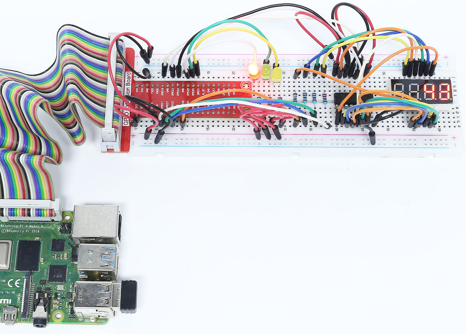
3.1.7 Ampel
Einführung
In diesem Projekt werden wir dreifarbige LED-Lichter verwenden, um den Wechsel der Ampeln zu realisieren, und eine vierstellige 7-Segment-Anzeige wird verwendet, um das Timing jedes Verkehrszustands anzuzeigen.
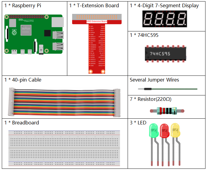
Komponenten
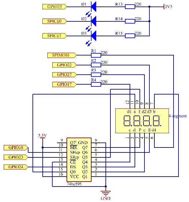
Schematische Darstellung
T-Karte Name |
physisch |
wiringPi |
BCM |
GPIO17 |
Pin 11 |
0 |
17 |
GPIO27 |
Pin 13 |
2 |
27 |
GPIO22 |
Pin 15 |
3 |
22 |
SPIMOSI |
Pin 19 |
12 |
10 |
GPIO18 |
Pin 12 |
1 |
18 |
GPIO23 |
Pin 16 |
4 |
23 |
GPIO24 |
Pin 18 |
5 |
24 |
GPIO25 |
Pin 22 |
6 |
25 |
SPICE0 |
Pin 24 |
10 |
8 |
SPICE1 |
Pin 26 |
11 |
7 |
Experimentelle Verfahren
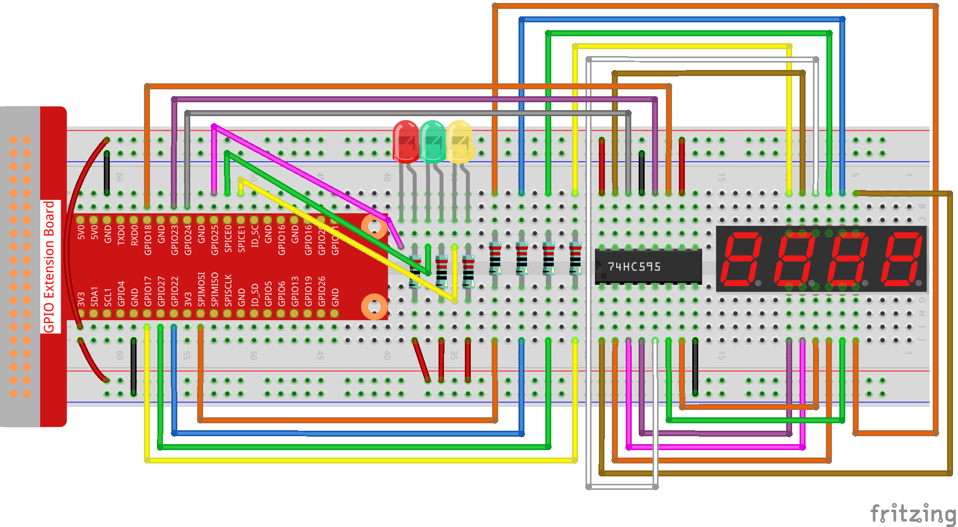
Schritt 1: Bauen Sie die Schaltung auf.
Für Benutzer in C-Sprache
Schritt 2: Verzeichnis wechseln.
cd ~/davinci-kit-for-raspberry-pi/c/3.1.7/
Schritt 3: Kompilieren.
gcc 3.1.7_TrafficLight.c -lwiringPi
Schritt 4: Ausführen.
sudo ./a.out
Während die Kode ausgeführt wird, simulieren LEDs den Farbwechsel von Ampeln. Zuerst leuchtet die rote LED 60 Sekunden lang, dann leuchtet die grüne LED 30 Sekunden lang. Als nächstes leuchtet die gelbe LED 5 Sekunden lang auf. Danach leuchtet die rote LED erneut für 60s. Auf diese Weise wird diese Reihe von Aktionen wiederholt ausgeführt.
Code Erklärung
#define     SDI     5
#define     RCLK    4
#define     SRCLK    1

const int placePin[] = {12, 3, 2, 0};
unsigned char number[] = {0xc0, 0xf9, 0xa4, 0xb0, 0x99, 0x92, 0x82, 0xf8, 0x80, 0x90};

void pickDigit(int digit);
void hc595_shift(int8_t data);
void clearDisplay();
void display();
Diese Codes werden verwendet, um die Funktion der Zahlenanzeige von 4-stelligen 7-Segment-Anzeigen zu realisieren. Siehe 1.1.5 4-stellige 7-Segment-Anzeige des Dokuments für weitere Details. Hier verwenden wir die Codes, um den Countdown der Ampelzeit anzuzeigen.
const int ledPin[]={6,10,11};

int colorState = 0;

void lightup()
{
    for(int i=0;i<3;i++){
        digitalWrite(ledPin[i],HIGH);
    }
    digitalWrite(ledPin[colorState],LOW);
}
Die Kode dienen zum Ein- und Ausschalten der LED.
int greenLight = 30;
int yellowLight = 5;
int redLight = 60;
int colorState = 0;
char *lightColor[]={"Red","Green","Yellow"};
int counter = 60;

void timer(int  timer1){       //Timer function
    if(timer1 == SIGALRM){
        counter --;
        alarm(1);
        if(counter == 0){
            if(colorState == 0) counter = greenLight;
            if(colorState == 1) counter = yellowLight;
            if(colorState == 2) counter = redLight;
            colorState = (colorState+1)%3;
        }
        printf("counter : %d \t light color: %s \n",counter,lightColor[colorState]);
    }
}
Die Codes dienen zum Ein- und Ausschalten des Timers. Weitere Informationen finden Sie unter 1.1.5 4-stellige 7-Segment-Anzeige . Wenn der Timer hier auf Null zurückkehrt, wird colorState auf LED umgeschaltet und dem Timer wird ein neuer Wert zugewiesen.
void loop()
{
    while(1){
    display();
    lightup();
    }
}

int main(void)
{
    //…
    signal(SIGALRM,timer);
    alarm(1);
    loop();
    return 0;
}
Der Timer wird in der Funktion main() gestartet.
Verwenden Sie in der Funktion loop() die Schleife while(1) und rufen Sie die Funktionen von 4-stelligem 7-Segment und LED auf.
Für Python-Sprachbenutzer
Schritt 2: Verzeichnis wechseln.
cd ~/davinci-kit-for-raspberry-pi/python/
Schritt 3: Ausführen.
sudo python3 3.1.7_TrafficLight.py
Während die Kode ausgeführt wird, simulieren LEDs den Farbwechsel von Ampeln. Zuerst leuchtet die rote LED 60 Sekunden lang, dann leuchtet die grüne LED 30 Sekunden lang. Als nächstes leuchtet die gelbe LED 5 Sekunden lang auf. Danach leuchtet die rote LED erneut für 60s. Auf diese Weise wird diese Reihe von Aktionen wiederholt ausgeführt. Währenddessen zeigt die 4-stellige 7-Segment-Anzeige kontinuierlich die Countdown-Zeit an.
Code
Bemerkung
Sie können den folgenden Code Ändern/Zurücksetzen/Kopieren/Ausführen/Stoppen . Zuvor müssen Sie jedoch zu einem Quellcodepfad wie davinci-kit-for-raspberry-pi/python gehen.
import RPi.GPIO as GPIO
import time
import threading

#define the pins connect to 74HC595
SDI   = 24      #serial data input(DS)
RCLK  = 23     #memory clock input(STCP)
SRCLK = 18      #shift register clock input(SHCP)
number = (0xc0,0xf9,0xa4,0xb0,0x99,0x92,0x82,0xf8,0x80,0x90)

placePin = (10,22,27,17)
ledPin =(25,8,7)

greenLight = 30
yellowLight = 5
redLight = 60
lightColor=("Red","Green","Yellow")

colorState=0
counter = 60
timer1 = 0


def setup():
    GPIO.setmode(GPIO.BCM)
    GPIO.setup(SDI, GPIO.OUT)
    GPIO.setup(RCLK, GPIO.OUT)
    GPIO.setup(SRCLK, GPIO.OUT)
    for pin in placePin:
        GPIO.setup(pin,GPIO.OUT)
    for pin in ledPin:
        GPIO.setup(pin,GPIO.OUT)
    global timer1
    timer1 = threading.Timer(1.0,timer)
    timer1.start()

def clearDisplay():
    for i in range(8):
        GPIO.output(SDI, 1)
        GPIO.output(SRCLK, GPIO.HIGH)
        GPIO.output(SRCLK, GPIO.LOW)
    GPIO.output(RCLK, GPIO.HIGH)
    GPIO.output(RCLK, GPIO.LOW)

def hc595_shift(data):
    for i in range(8):
        GPIO.output(SDI, 0x80 & (data << i))
        GPIO.output(SRCLK, GPIO.HIGH)
        GPIO.output(SRCLK, GPIO.LOW)
    GPIO.output(RCLK, GPIO.HIGH)
    GPIO.output(RCLK, GPIO.LOW)

def pickDigit(digit):
    for i in placePin:
        GPIO.output(i,GPIO.LOW)
    GPIO.output(placePin[digit], GPIO.HIGH)

def timer():        #timer function
    global counter
    global colorState
    global timer1
    timer1 = threading.Timer(1.0,timer)
    timer1.start()
    counter-=1
    if (counter is 0):
        if(colorState is 0):
            counter= greenLight
        if(colorState is 1):
            counter=yellowLight
        if (colorState is 2):
            counter=redLight
        colorState=(colorState+1)%3
    print ("counter : %d    color: %s "%(counter,lightColor[colorState]))

def lightup():
    global colorState
    for i in range(0,3):
        GPIO.output(ledPin[i], GPIO.HIGH)
    GPIO.output(ledPin[colorState], GPIO.LOW)

def display():
    global counter

    a = counter % 10000//1000 + counter % 1000//100
    b = counter % 10000//1000 + counter % 1000//100 + counter % 100//10
    c = counter % 10000//1000 + counter % 1000//100 + counter % 100//10 + counter % 10

    if (counter % 10000//1000 == 0):
        clearDisplay()
    else:
        clearDisplay()
        pickDigit(3)
        hc595_shift(number[counter % 10000//1000])

    if (a == 0):
        clearDisplay()
    else:
        clearDisplay()
        pickDigit(2)
        hc595_shift(number[counter % 1000//100])

    if (b == 0):
        clearDisplay()
    else:
        clearDisplay()
        pickDigit(1)
        hc595_shift(number[counter % 100//10])

    if(c == 0):
        clearDisplay()
    else:
        clearDisplay()
        pickDigit(0)
        hc595_shift(number[counter % 10])

def loop():
    while True:
        display()
        lightup()

def destroy():   # When "Ctrl+C" is pressed, the function is executed.
    global timer1
    GPIO.cleanup()
    timer1.cancel()      #cancel the timer

if __name__ == '__main__': # Program starting from here
    setup()
    try:
        loop()
    except KeyboardInterrupt:
        destroy()
Code Erklärung
SDI   = 24      #serial data input(DS)
RCLK  = 23     #memory clock input(STCP)
SRCLK = 18      #shift register clock input(SHCP)
number = (0xc0,0xf9,0xa4,0xb0,0x99,0x92,0x82,0xf8,0x80,0x90)
placePin = (10,22,27,17)

def clearDisplay():
def hc595_shift(data):
def pickDigit(digit):
def display():
Diese Codes werden verwendet, um die Funktion der Zahlenanzeige des 4-stelligen 7-Segments zu realisieren. Siehe 1.1.5 4-stellige 7-Segment-Anzeige des Dokuments für weitere Details. Hier verwenden wir die Codes, um den Countdown der Ampelzeit anzuzeigen.
ledPin =(25,8,7)
colorState=0

def lightup():
    global colorState
    for i in range(0,3):
        GPIO.output(ledPin[i], GPIO.HIGH)
    GPIO.output(ledPin[colorState], GPIO.LOW)
Die Kode dienen zum Ein- und Ausschalten der LED.
greenLight = 30
yellowLight = 5
redLight = 60
lightColor=("Red","Green","Yellow")

colorState=0
counter = 60
timer1 = 0

def timer():        #timer function
    global counter
    global colorState
    global timer1
    timer1 = threading.Timer(1.0,timer)
    timer1.start()
    counter-=1
    if (counter is 0):
        if(colorState is 0):
            counter= greenLight
        if(colorState is 1):
            counter=yellowLight
        if (colorState is 2):
            counter=redLight
        colorState=(colorState+1)%3
    print ("counter : %d    color: %s "%(counter,lightColor[colorState]))
Die Codes dienen zum Ein- und Ausschalten des Timers. Weitere Informationen finden Sie unter 1.1.5 4-stellige 7-Segment-Anzeige . Wenn der Timer hier auf Null zurückkehrt, wird colorState auf LED umgeschaltet und dem Timer wird ein neuer Wert zugewiesen.
def setup():
    # ...
    global timer1
    timer1 = threading.Timer(1.0,timer)
    timer1.start()

def loop():
    while True:
        display()
        lightup()

def destroy():   # When "Ctrl+C" is pressed, the function is executed.
    global timer1
    GPIO.cleanup()
    timer1.cancel()      #cancel the timer

if __name__ == '__main__': # Program starting from here
    setup()
    try:
        loop()
    except KeyboardInterrupt:
        destroy()
Starten Sie in der Funktion setup() den Timer. In der Funktion loop() wird eine While True verwendet: Rufen Sie die relativen Funktionen von 4-stelligem 7-Segment und LED kreisförmig auf.
Phänomen Bild