Read from MPU9250
After calibrating the MPU9250 chip, let’s print the data read by the MPU9250 chip.
TIPS
A block to output the data read by the MPU9250 chip.
First Parameter: Choose accelerometer, gyroscope or magnetometer.
Second Parameter: Choose x, y or z.
For example, if you select accelerometer and x, the acceleration value of X Sense HAT on the x-axis will be returned.

The Print function can print data such as variables and text for easy debugging.

After clicking on the bug icon in the bottom left corner, the data printed by the print function will appear in the Debug Monitor.

EXAMPLE
Accelerometer and Gyroscope
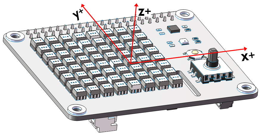
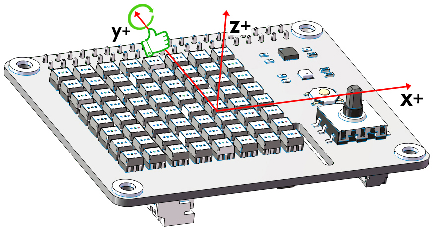
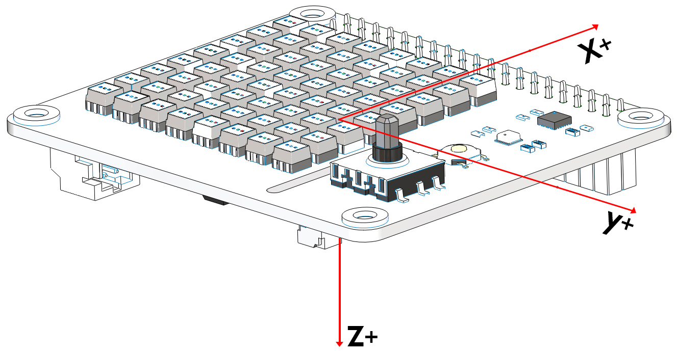
The following diagram shows the coordinate system for the Acelerometer and Gyroscope.
Note
Note the positive direction on each axis.
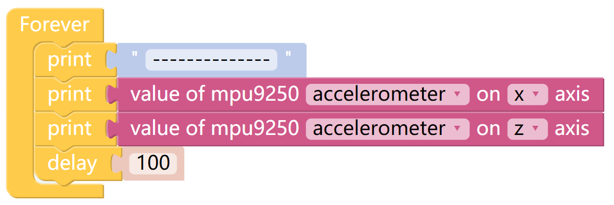
Accelerometer
Through the Accelerometer, we can read the acceleration values of the X Sense HAT on the different axes in g.
Place the X Sense HAT horizontally. At this time, the X Sense HAT will be subjected to a vertical downward acceleration of gravity, which is g (g=9.80665 N/kg).
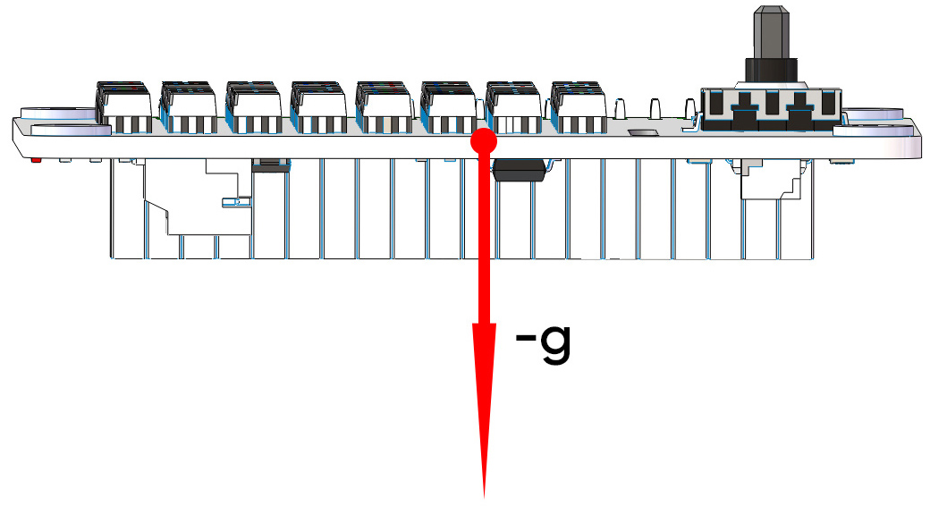
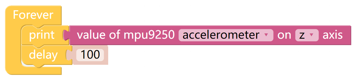
When we print the acceleration value on the z-axis, the Debug Monitor will display a value around -1. Since the acceleration value is on the negative half axis of the z-axis, the unit is negative.
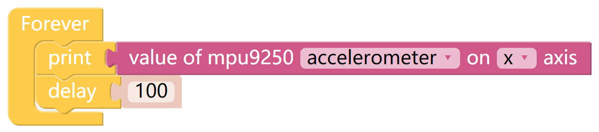
Rotate the X Sense HAT clockwise around the y-axis. At this time, the gravitational acceleration received by the X Sense HAT can be decomposed into an acceleration on the x-axis and an acceleration on the z-axis, we can print these 2 accelerations on the Debug Monitor.
Gyroscope
Through the Gyroscope, we can read the angular velocity values of X Sense HAT on different coordinate axes, the unit size is degrees/second.
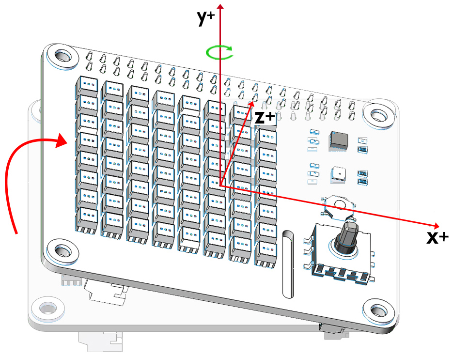
The judgment of the unit symbol follows the right-hand spiral rule. Hold the axis with your right hand and the thumb points in the direction of the positive semi-axis.
At this time, the direction pointed by the four fingers is the positive direction of the angular velocity value.
Print the angular velocity value on the y-axis.
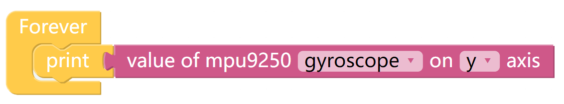
Rotate the X Sense HAT clockwise around the y-axis. Because the angle of the X Sense HAT changes, the angular velocity value of the y-axis is generated and will be printed on Debug Monitor. According to the right-hand screw rule, its unit is positive.
Magnetometer
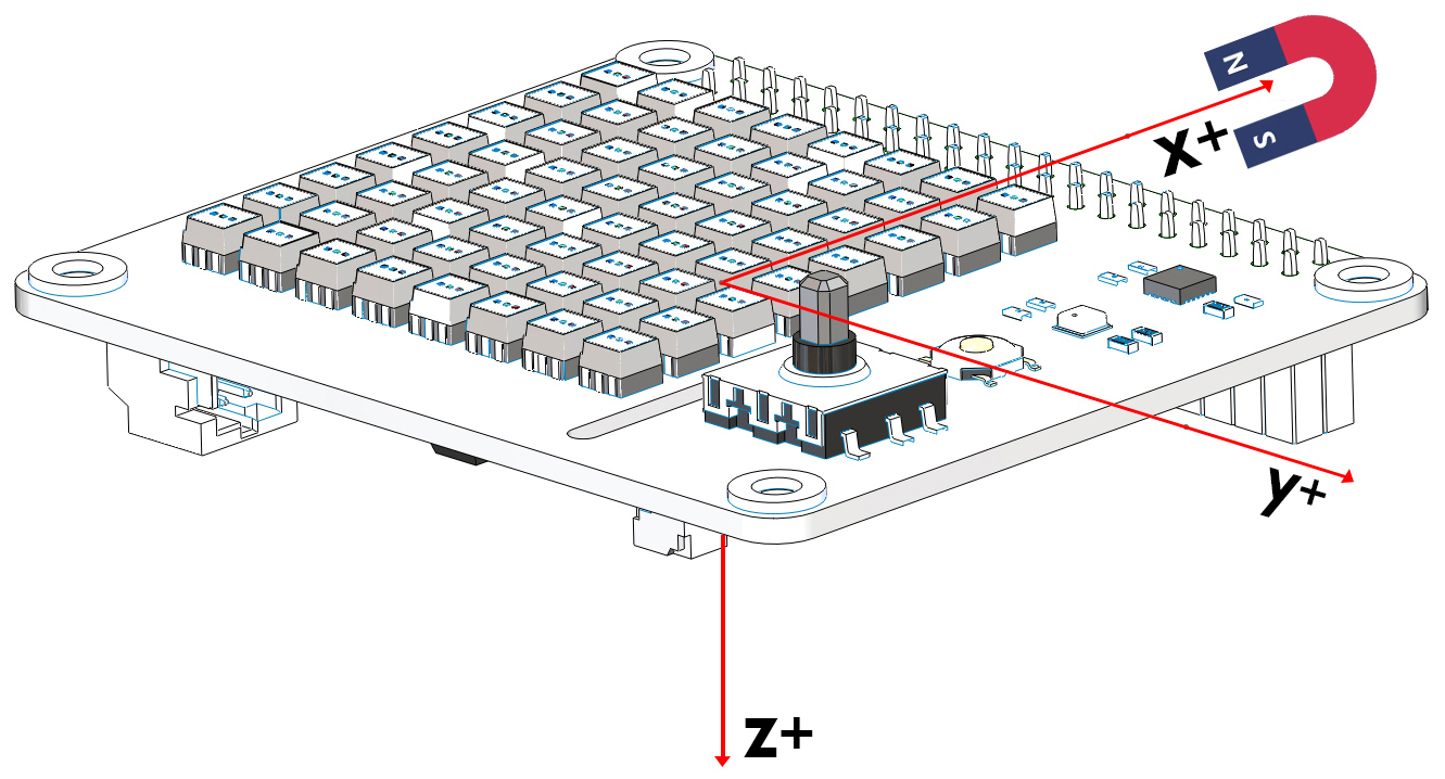
The following diagram shows the coordinate system for the Magnetometer.
Note
Note the positive direction on each axis.
Through the magnetometer, we can read the magnetic field strength of X Sense HAT on different coordinate axes, the unit size is 15μT.
We can put a magnet on the positive x-axis of the X Sense HAT.
Then print the value of the magnetic field strength on the positive semi-axis of the x-axis (in positive unit).