Note
Bonjour et bienvenue dans la Communauté Facebook des passionnés de Raspberry Pi, Arduino et ESP32 de SunFounder ! Plongez plus profondément dans l’univers des Raspberry Pi, Arduino et ESP32 avec d’autres passionnés.
Pourquoi rejoindre ?
Support d’experts : Résolvez les problèmes après-vente et les défis techniques avec l’aide de notre communauté et de notre équipe.
Apprendre et partager : Échangez des astuces et des tutoriels pour améliorer vos compétences.
Aperçus exclusifs : Accédez en avant-première aux annonces de nouveaux produits et aux aperçus.
Réductions spéciales : Profitez de réductions exclusives sur nos produits les plus récents.
Promotions festives et cadeaux : Participez à des cadeaux et des promotions de vacances.
👉 Prêt à explorer et à créer avec nous ? Cliquez [Ici] et rejoignez-nous aujourd’hui !
1.3.3 Relais
Introduction
Dans ce projet, nous allons apprendre à utiliser un relais. C’est l’un des composants couramment utilisés dans les systèmes de contrôle automatique. Lorsque la tension, le courant, la température, la pression, etc., atteignent, dépassent ou sont inférieurs à la valeur prédéterminée, le relais connecte ou interrompt le circuit, pour contrôler et protéger l’équipement.
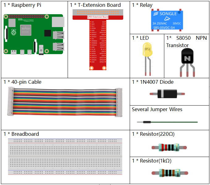
Composants Nécessaires
Dans ce projet, nous avons besoin des composants suivants.
Il est certainement pratique d’acheter un kit complet, voici le lien :
Nom |
ARTICLES DANS CE KIT |
LIEN |
|---|---|---|
Kit Raphael |
337 |
Vous pouvez également les acheter séparément via les liens ci-dessous.
INTRODUCTION DES COMPOSANTS |
LIEN D’ACHAT |
|---|---|
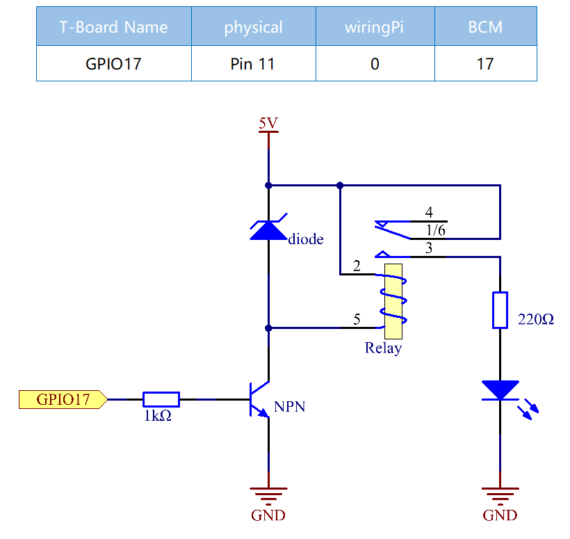
Schéma de Câblage
Procédures Expérimentales
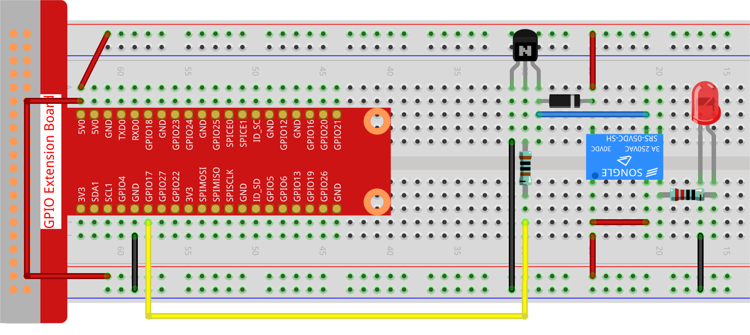
Étape 1 : Construisez le circuit.
Étape 2 : Ouvrez le fichier de code.
cd ~/raphael-kit/python-pi5
Étape 3 : Exécutez.
sudo python3 1.3.3_Relay_zero.py
- Pendant l’exécution du code, la LED s’allume. De plus, vous pouvez entendre un
- tic-tac causé par l’ouverture du contact normalement fermé et la fermeture du
contact normalement ouvert.
Avertissement
Si vous recevez le message d’erreur RuntimeError: Cannot determine SOC peripheral base address, veuillez consulter Si « gpiozero » ne fonctionne pas.
Code
Note
Vous pouvez Modifier/Réinitialiser/Copier/Exécuter/Arrêter le code ci-dessous. Mais avant cela, vous devez aller dans le chemin du code source comme raphael-kit/python-pi5. Après avoir modifié le code, vous pouvez l’exécuter directement pour voir l’effet.
#!/usr/bin/env python3
from gpiozero import OutputDevice  # Import the class for controlling GPIO pins
from time import sleep  # Import the sleep function for delay

# Initialize the relay connected to GPIO pin 17, starting in the 'off' state
relay = OutputDevice(17, initial_value=False)

try:
    # Loop to continuously toggle the relay's state every second
    while True:
        print('Relay open...')  # Inform that the relay is being activated
        relay.on()  # Turn on the relay (assuming active low configuration)
        sleep(1)   # Maintain the relay in the on state for 1 second

        print('...Relay close')  # Inform that the relay is being deactivated
        relay.off()  # Turn off the relay
        sleep(1)   # Maintain the relay in the off state for 1 second

except KeyboardInterrupt:
    # Handle a keyboard interrupt (Ctrl+C) to exit the loop
    relay.off()  # Ensure the relay is turned off before exiting
    pass
Explication du Code
Importer
OutputDevicedegpiozeropour contrôler les broches GPIO etsleepdetimepour ajouter des délais.#!/usr/bin/env python3 from gpiozero import OutputDevice # Import the class for controlling GPIO pins from time import sleep # Import the sleep function for delay
Initializes an
OutputDeviceobject for the relay connected to GPIO pin 17. Theinitial_value=Falsesets the relay to theoffstate initially (assuming active low configuration).# Initialize the relay connected to GPIO pin 17, starting in the 'off' state relay = OutputDevice(17, initial_value=False)
Inside the
tryblock, awhile Trueloop continuously toggles the relay’s state. The relay is turned on and off with a 1-second delay between each state, accompanied by console print statements.try: # Loop to continuously toggle the relay's state every second while True: print('Relay open...') # Inform that the relay is being activated relay.on() # Turn on the relay (assuming active low configuration) sleep(1) # Maintain the relay in the on state for 1 second print('...Relay close') # Inform that the relay is being deactivated relay.off() # Turn off the relay sleep(1) # Maintain the relay in the off state for 1 second
Attrape une interruption clavier (comme Ctrl+C) pour permettre une terminaison en douceur du script. Le relais est éteint avant de sortir du script.
except KeyboardInterrupt:
  # Handle a keyboard interrupt (Ctrl+C) to exit the loop
  relay.off()  # Ensure the relay is turned off before exiting
  pass