Note
Hello, welcome to the SunFounder Raspberry Pi & Arduino & ESP32 Enthusiasts Community on Facebook! Dive deeper into Raspberry Pi, Arduino, and ESP32 with fellow enthusiasts.
Why Join?
Expert Support: Solve post-sale issues and technical challenges with help from our community and team.
Learn & Share: Exchange tips and tutorials to enhance your skills.
Exclusive Previews: Get early access to new product announcements and sneak peeks.
Special Discounts: Enjoy exclusive discounts on our newest products.
Festive Promotions and Giveaways: Take part in giveaways and holiday promotions.
👉 Ready to explore and create with us? Click [here] and join today!
2.1.7 Potentiometer(MCP3008)
Note

Depending on your kit version, please identify whether you have ADC0834 or MCP3008 and proceed with the matching section.
Introduction
The ADC function is used to convert analog signals into digital values. In this experiment, we use the MCP3008 ADC chip to perform this conversion. A potentiometer is used to generate a variable voltage, which changes the physical quantity. The MCP3008 then converts this analog voltage into a digital value that can be read and processed by the Raspberry Pi.
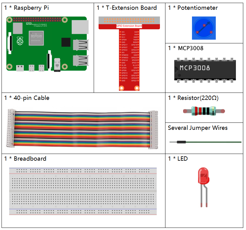
Required Components
In this project, we need the following components.
It’s definitely convenient to buy a whole kit, here’s the link:
Name |
ITEMS IN THIS KIT |
LINK |
|---|---|---|
Raphael Kit |
337 |
You can also buy them separately from the links below.
COMPONENT INTRODUCTION |
PURCHASE LINK |
|---|---|
- |
Schematic Diagram
T-Board Name |
physical |
WiringPi |
BCM |
|---|---|---|---|
SPICE0 |
pin24 |
10 |
8 |
SPIMOSI |
pin19 |
12 |
10 |
SPIMISO |
pin21 |
13 |
9 |
SPISCLK |
pin23 |
14 |
11 |
GPIO22 |
pin15 |
3 |
22 |

Experimental Procedures
Step 1: Build the circuit.
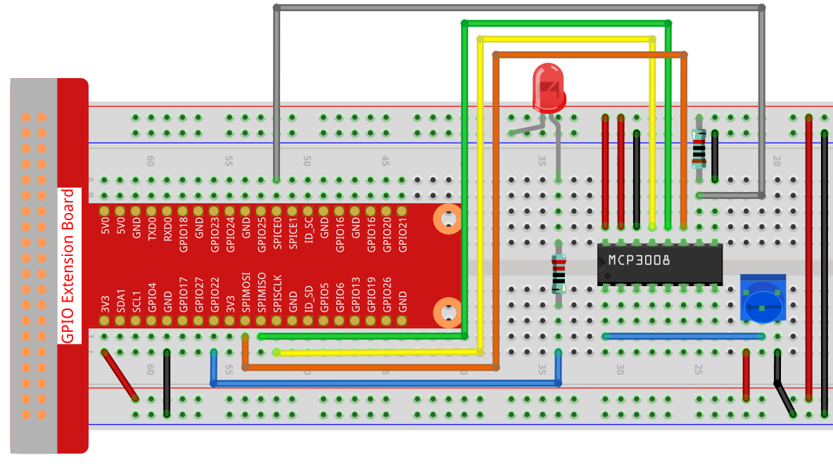
Note
Please place the chip by referring to the corresponding position depicted in the picture. Note that the grooves on the chip should be on the left when it is placed.
Step 2: Set up the SPI interface and install the spidev library (see SPI Configuration for detailed instructions). If you have already completed these steps, you can skip this.
Step 3: Open the code file
cd ~/raphael-kit/python
Step 4: Run.
sudo python3 2.1.7-2_Potentiometer.py
After the code runs, rotate the knob on the potentiometer, the intensity of LED will change accordingly.
Warning
If there is an error prompt RuntimeError: Cannot determine SOC peripheral base address, please refer to If gpiozero doesn’t work.
Code
Note
You can Modify/Reset/Copy/Run/Stop the code below. But before that, you need to go to source code path like raphael-kit/python. After modifying the code, you can run it directly to see the effect.
#!/usr/bin/env python3

import spidev
import time
import RPi.GPIO as GPIO

# GPIO pin for PWM output
PWM_PIN = 22

# Setup GPIO
GPIO.setmode(GPIO.BCM)
GPIO.setup(PWM_PIN, GPIO.OUT)

# Initialize PWM on GPIO22 at 1000Hz
pwm = GPIO.PWM(PWM_PIN, 1000)
pwm.start(0)  # Start with 0% duty cycle

# Initialize SPI
spi = spidev.SpiDev()
spi.open(0, 0)  # Bus 0, CE0
spi.max_speed_hz = 1000000

def read_adc(channel):
    """
    Read analog value from MCP3008
    :param channel: ADC channel (0-7)
    :return: 10-bit integer (0-1023)
    """
    if channel < 0 or channel > 7:
        return -1
    adc = spi.xfer2([1, (8 + channel) << 4, 0])
    value = ((adc[1] & 3) << 8) | adc[2]
    return value

def MAP(x, in_min, in_max, out_min, out_max):
    """
    Map a value from one range to another
    """
    return (x - in_min) * (out_max - out_min) / (in_max - in_min) + out_min

try:
    while True:
        # Read analog value from CH0
        res = read_adc(0)
        print('res = %d' % res)

        # Convert to 0–100% duty cycle
        duty_cycle = MAP(res, 0, 1023, 0, 100)

        # Update PWM duty cycle
        pwm.ChangeDutyCycle(duty_cycle)

        time.sleep(0.2)

except KeyboardInterrupt:
    pass

finally:
    pwm.stop()
    GPIO.cleanup()
    spi.close()
Code Explanation
RPi.GPIOis used to generate PWM signals to control an LED.spidevis used for SPI communication with the MCP3008.timeis used to add delays in the loop.#!/usr/bin/env python3 import spidev import time import RPi.GPIO as GPIO
Configure GPIO pin 22 for PWM output using
RPi.GPIO. Set up SPI communication with the MCP3008 (Bus 0, CE0) at 1 MHz.PWM_PIN = 22 GPIO.setmode(GPIO.BCM) GPIO.setup(PWM_PIN, GPIO.OUT) pwm = GPIO.PWM(PWM_PIN, 1000) # 1kHz frequency pwm.start(0) # Start with 0% duty cycle spi = spidev.SpiDev() spi.open(0, 0) spi.max_speed_hz = 1000000
This function reads analog data from the MCP3008 on the specified channel (0–7) using the SPI protocol. The result is a 10-bit integer ranging from 0 to 1023.
def read_adc(channel):
    if channel < 0 or channel > 7:
        return -1
    adc = spi.xfer2([1, (8 + channel) << 4, 0])
    value = ((adc[1] & 3) << 8) | adc[2]
    return value
This function maps a value from one numerical range to another. It’s used to scale ADC values to PWM duty cycle percentages.
def MAP(x, in_min, in_max, out_min, out_max):
    return (x - in_min) * (out_max - out_min) / (in_max - in_min) + out_min
In the main loop, the program continuously reads analog data from channel 0 of the MCP3008, maps the value to a PWM range (0–100), and sets the LED brightness accordingly. The loop updates every 0.2 seconds. If interrupted (e.g., Ctrl+C), the program stops the PWM signal and cleans up the GPIO configuration.
try:
    while True:
        res = read_adc(0)
        print('res = %d' % res)

        duty_cycle = MAP(res, 0, 1023, 0, 100)
        pwm.ChangeDutyCycle(duty_cycle)

        time.sleep(0.2)

except KeyboardInterrupt:
    pass

finally:
    pwm.stop()
    GPIO.cleanup()
    spi.close()