2.2.4 Reed Switch Module
Introduction
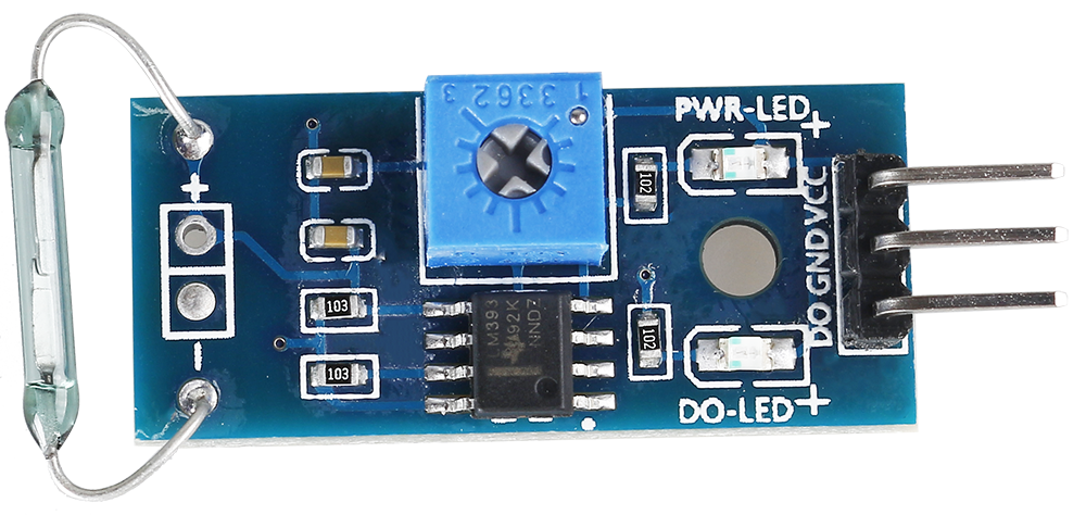
In this project, we will learn about the reed switch, which is an electrical switch that operates by means of an applied magnetic field.
Required Components
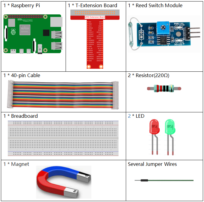
In this project, we need the following components.
It’s definitely convenient to buy a whole kit, here’s the link:
Name |
ITEMS IN THIS KIT |
LINK |
|---|---|---|
Raphael Kit |
337 |
You can also buy them separately from the links below.
COMPONENT INTRODUCTION |
PURCHASE LINK |
|---|---|
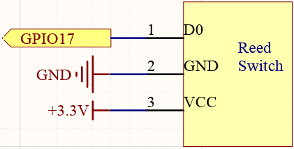
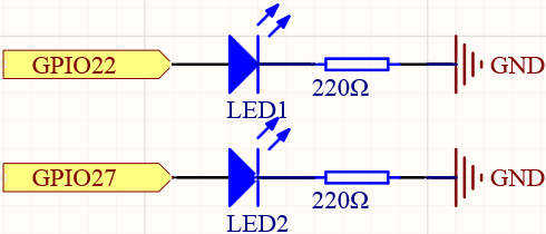
Schematic Diagram
T-Board Name |
physical |
wiringPi |
BCM |
GPIO17 |
Pin 11 |
0 |
17 |
GPIO27 |
Pin 13 |
2 |
27 |
GPIO22 |
Pin 15 |
3 |
22 |
Experimental Procedures
Step 1: Build the circuit.
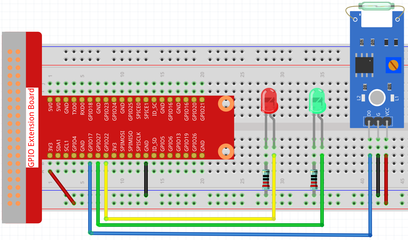
Step 2: Go to the folder of the code.
cd ~/raphael-kit/nodejs/
Step 3: Run the code.
sudo node reed_switch_module.js
The green LED will light up when the code is run. If a magnet is placed close to the reed switch module, the red LED lights up; take away the magnet and the green LED lights up again.
Code
const Gpio = require('pigpio').Gpio;

const led1 = new Gpio(22, {mode: Gpio.OUTPUT});
const led2 = new Gpio(27, {mode: Gpio.OUTPUT});

const reedSwitch = new Gpio(17, {
    mode: Gpio.INPUT,
    pullUpDown: Gpio.PUD_DOWN,
    edge: Gpio.EITHER_EDGE
});

reedSwitch.on('interrupt', (level) => {
    led1.digitalWrite(level);
    led2.digitalWrite(!level);
});
Code Explanation
const Gpio = require('pigpio').Gpio;

const reedSwitch = new Gpio(17, {
    mode: Gpio.INPUT,
    pullUpDown: Gpio.PUD_DOWN,
    edge: Gpio.EITHER_EDGE
});
Import the pigpio module, create a ReedPin object to control the IO port, set it to input mode, pull down (initially low level), and set an interrupt.
const led1 = new Gpio(22, {mode: Gpio.OUTPUT});
const led2 = new Gpio(27, {mode: Gpio.OUTPUT});
Create two objects led1, led2 to control the IO ports Gpio22 and Gpio27, and set them to output mode.
reedSwitch.on('interrupt', (level) => {
    led1.digitalWrite(level);
    led2.digitalWrite(!level);
});
When the interrupt is triggered, write the same level to led1, and write the opposite level to led2.