Note
Welcome to the SunFounder Raspberry Pi, Arduino & ESP32 Community on Facebook!
Get technical support and troubleshooting help.
Learn and share projects, tips, and tutorials.
Access early product previews and updates.
Enjoy exclusive discounts and giveaways.
👉 Join us here: [here]
Dual NVMe PIP
The Dual NVMe PIP (PCIe Peripheral Board), as defined by the Raspberry Pi Foundation, is a PCIe adapter designed specifically for NVMe solid-state drives.
The Raspberry Pi 5’s PCIe interface natively offers a single Gen2 x1 lane (500 MB/s). By integrating the ASM1182e PCIe switch chip, the Dual NVMe PIP expands this into two independent Gen2 x1 lanes, allowing you to connect:
Two M.2 NVMe SSDs, or
One M.2 NVMe SSD + one M.2 Hailo-8/8L AI accelerator
Key Notes:
Gen3 is not supported
Supports NVMe SSD sizes: 2230, 2242, 2260, 2280 (all in M.2 M-key slots)
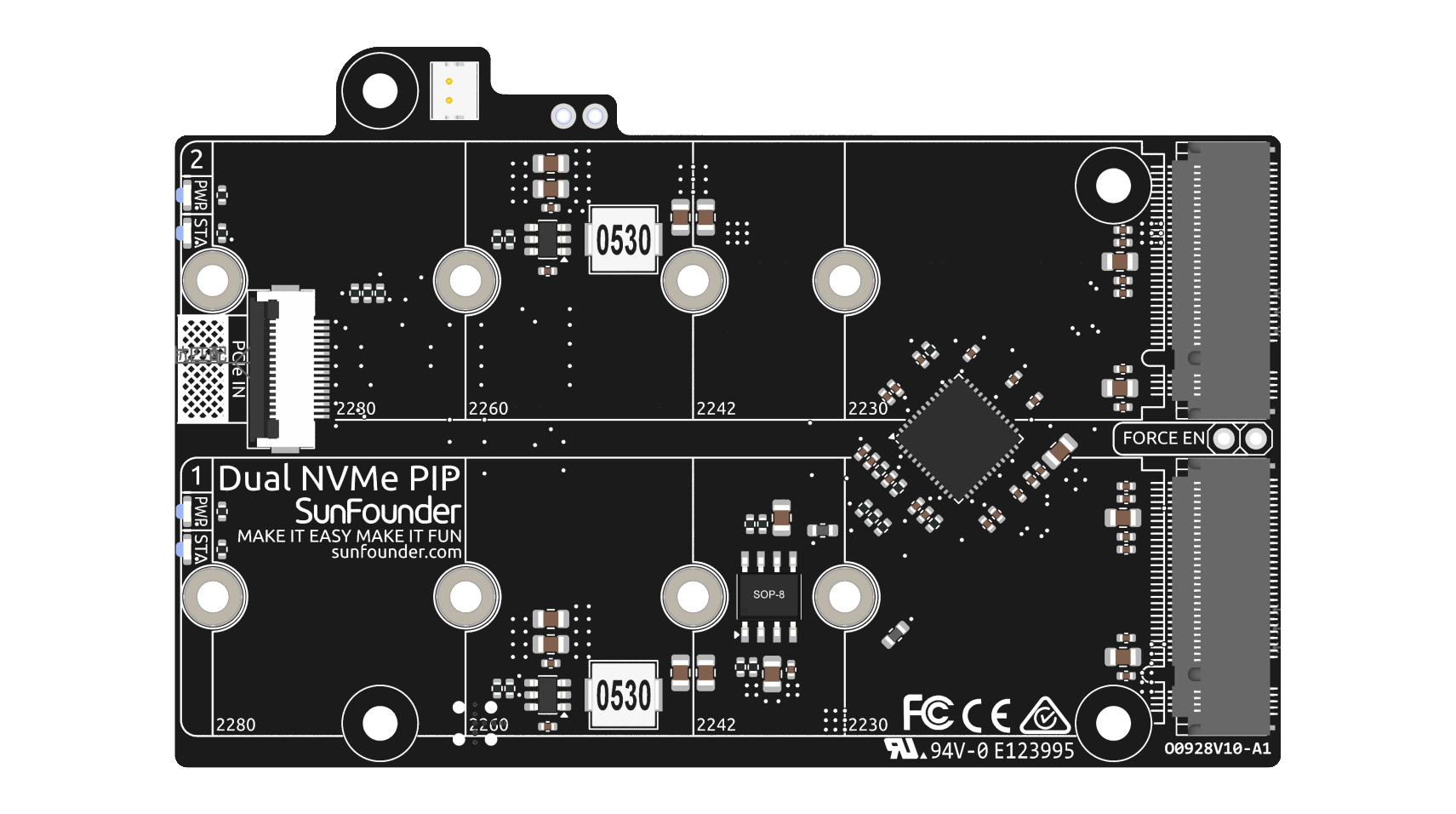
The board connects through a 16P 0.5mm reverse FFC (Flexible Flat Cable) or a custom impedance-matched FPC (Flexible Printed Circuit) cable.
STA: A Status LED indicator.
PWR: A Power LED indicator.
The onboard 3.3V power supply can support up to 3A output. However, since the Raspberry Pi PCIe interface is limited to providing 5V/1A output (equivalent to 5W), additional power for 3.3V/3A usage can be supplied through the J3 connector from a 5V source.
FORCE ENABLE: The onboard power supply is activated by the switch signal from the PCIe interface. After the Raspberry Pi is powered on, it sends a signal to turn on the 3.3V power supply. If some systems do not support the switch signal or for other reasons, you can short-circuit J4 FORCE ENABLE by soldering a wire between the two floating pads to force the onboard 3.3V power supply to power the NVMe.
About the Model
M.2 SSDs, known for their compact size, come in various types mainly differentiated by their keying (notch design on the connector) and the interface they use. Here are the primary types:
M.2 SATA SSDs: These use the SATA interface, similar to 2.5-inch SATA SSDs but in the smaller M.2 form factor. They are limited by the SATA III maximum speeds of around 600 MB/s. These SSDs are compatible with M.2 slots keyed for B and M keys.
M.2 NVMe SSDs: These SSDs use the NVMe protocol over PCIe lanes and are significantly faster than M.2 SATA SSDs. They are suitable for applications requiring high read/write speeds like gaming, video editing, and data-intensive tasks. These SSDs typically require M-keyed slots. These drives utilize the PCIe (Peripheral Component Interconnect Express) interface, with different versions like 3.0, 4.0, and 5.0. Each new version of PCIe effectively doubles the data transfer speed of its predecessor. However, the Raspberry Pi 5 uses a PCIe 3.0 interface, capable of delivering transfer speeds up to 3,500 MB/s.
M.2 SSDs come in three key types: B key, M key, and B+M key. However, later on, the B+M key was introduced, combining the functionalities of the B key and M key. As a result, it replaced the standalone B key. Please refer to the image below.
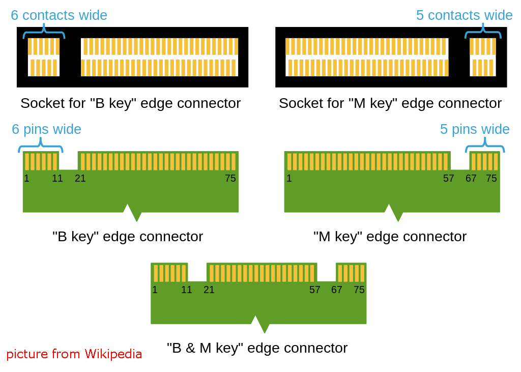
In general, M.2 SATA SSDs are B+M-keyed (can fit in sockets for B-keyed and M-keyed modules), while M.2 NVMe SSDs for PCIe 3.0 x4 lane are M-keyed.

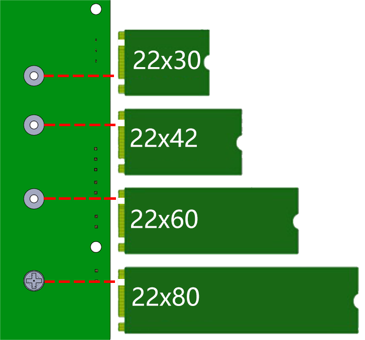
About the Length
M.2 modules come in different sizes and can also be utilized for Wi-Fi, WWAN, Bluetooth, GPS, and NFC.
Pironman 5 MAX supports four (PCIe Gen 2.0) NVMe M.2 SSD sizes based on their names: 2230, 2242, 2260, and 2280. The “22” is the width in millimeters (mm), and the two following numbers are the length. The longer the drive, the more NAND flash chips can be mounted; therefore, the more capacity.
Power
The onboard dual 3.3V power supply supports a maximum output of 3A (10W). Both power rails operate independently without interference.
FORCE ENABLE The onboard power supply is activated by the switch signal from the PCIe interface. After the Raspberry Pi boots up, the signal turns on the 3.3V power. If the system does not support the switch signal or due to other reasons, short the J4 FORCE EN jumper to forcibly enable the onboard 3.3V power for NVMe.
LED Each interface has independent power status indicators (PWR) and state indicators (STA).
Power Switch Convertor
Adding the Power Button
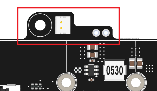
The Raspberry Pi 5 features a J2 jumper, situated between the RTC battery connector and the board edge. This breakout enables the addition of a custom power button to the Raspberry Pi 5 by connecting a Normally Open (NO) momentary switch across the two pads. Briefly engaging this switch mimics the onboard power button’s functionality.
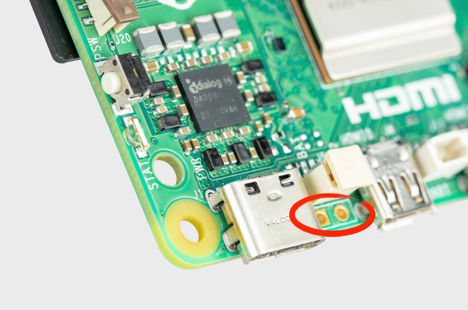
On the Pironman 5, there’s a Power Switch Converter that extends the J2 jumper to an external power button using two Pogo pins.
Now, the Raspberry Pi 5 can be powered on and off using the Power Button.
Power Cycling
Upon initially powering your Raspberry Pi 5, it will automatically turn on and boot into the operating system without the need to press the button.
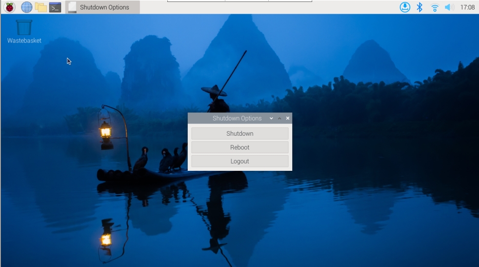
If running the Raspberry Pi Desktop, a brief press of the power button initiates a clean shutdown process. A menu will appear, offering options to shutdown, reboot, or logout. Selecting an option or pressing the power button again will start a clean shutdown.
Shutdown
If you run Raspberry Pi OS Desktop system, you can press the power button twice in quick succession to shutdown.
If you run Raspberry Pi OS Lite system without a desktop, press the power button a single time to initiate a shutdown.
To force a hard shutdown, press and hold the power button.
Power on
If the Raspberry Pi board is shut down, but still powered, single-press to power on from a shutdown state.
Note
If you are running a system that does not support a shutdown button, you can hold it for 5 seconds to force a hard shutdown, and single-press to power on from a shutdown state.