Note
Welcome to the SunFounder Raspberry Pi, Arduino & ESP32 Community on Facebook!
Get technical support and troubleshooting help.
Learn and share projects, tips, and tutorials.
Access early product previews and updates.
Enjoy exclusive discounts and giveaways.
👉 Join us here: [here]
IO Expander
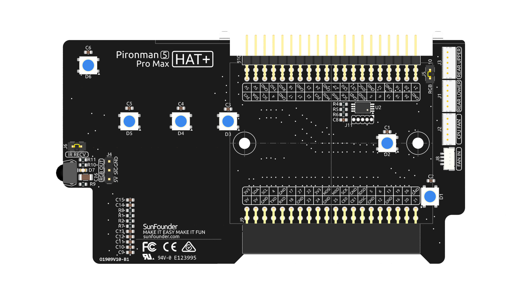
RGB LEDs
The board features 18 WS2812B addressable RGB LEDs: 6 onboard and 12 integrated into the RGB fans, offering customizable control. Users can turn them on or off, change the color, adjust the brightness, switch display modes, and set the speed of changes.
RGB Control Pin
The RGB LED is driven by SPI and connected to GPIO10, which is also the SPI MOSI pin. The two pins shown are used to connect the RGB to GPIO10. If not needed, the jumper can be removed.

RGB OUT Pins
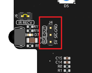
The WS2812 RGB LEDs support serial connection, allowing for the attachment of an external RGB LED strip. Connect the SIG pin to the external strip’s DIN pin for expansion.
The board features 18 WS2812B addressable RGB LEDs: 6 onboard and 12 integrated into the RGB fans. Connect additional LEDs and update the count using:
sudo pironman5 --rgb-led-count [quantity]
Example:
sudo pironman5 --rgb-led-count 24
OLED Screen Connector
The OLED screen connector, with an address of 0x3C, is a key feature.
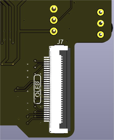
If the OLED Screen is not displaying or displaying incorrectly, you can follow these steps to troubleshoot the issue:
Check if the FPC cable of the OLED Screen is properly connected.
Use the following command to view the program’s run logs and check for error messages.
cat /var/log/pironman5/pironman5.logAlternatively, use the following command to check if the OLED’s i2c address 0x3C is recognized:
sudo i2cdetect -y 1
If the first two steps don’t reveal any issues, try restarting the pironman5 service to see if that resolves the problem.
sudo systemctl restart pironman5.service
Infrared Receiver
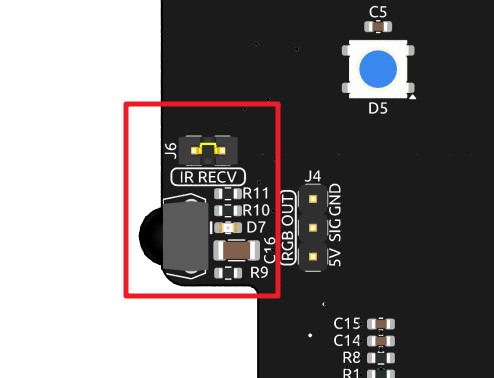
Model: IRM-56384, operating at 38KHz.
Connection: The IR receiver connects to GPIO13.
D7: An infrared reception indicator that blinks upon signal detection.
J6: A pin for enabling the infrared function. By default, a jumper cap is inserted for immediate functionality. Remove the cap to free GPIO13 if the IR receiver is not in use.
To utilize the IR receiver, verify its connection and install the necessary module:
Test the connection:
sudo ls /dev |grep lirc
Install the
lircmodule:sudo apt-get install lirc -y
Now, test the IR Receiver by running the following command.
mode2 -d /dev/lirc0
After running the command, press a button on the remote control, and the code of that button will be printed.
RGB Fan Pins
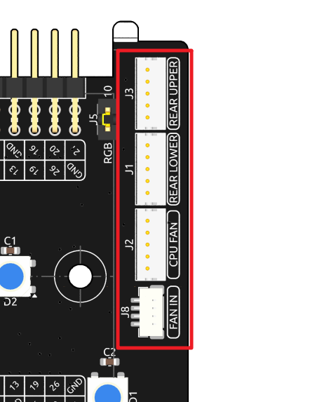
The IO expansion board supports up to three 5V PWM fans. All fans are controlled together.
The fan control signal is connected to the FAN IN port on the IO expansion board, and then output from the three dedicated fan ports. These ports are numbered from top to bottom as REAR UPPER , REAR LOWER , and CPU FAN. Please connect them according to the silk screen, otherwise it will affect the RGB control on the fan.
Pin Headers
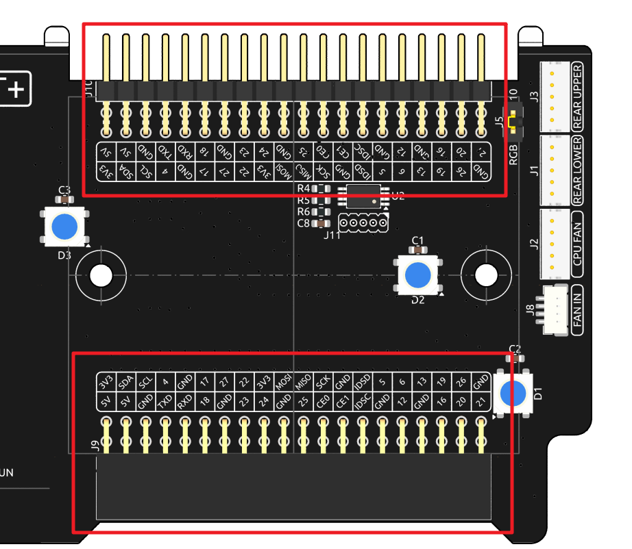
Two right-angle header connectors extend the Raspberry Pi’s GPIO, but note that the IR receiver, RGB LED, and fan occupy some pins. Remove the corresponding jumper caps to utilize these pins for other functions.
Pironman 5 MAX |
Raspberry Pi 5 |
|---|---|
IR Receiver(Optional) |
GPIO13 |
OLED SDA |
SDA |
OLED SCL |
SCL |
FAN(Optional) |
GPIO6 |
FLED(Optional) |
GPIO5 |
RGB(Optional) |
GPIO10 |