Note
Welcome to the SunFounder Raspberry Pi, Arduino & ESP32 Community on Facebook!
Get technical support and troubleshooting help.
Learn and share projects, tips, and tutorials.
Access early product previews and updates.
Enjoy exclusive discounts and giveaways.
👉 Join us here: [here]
IO Expander
RGB LEDs
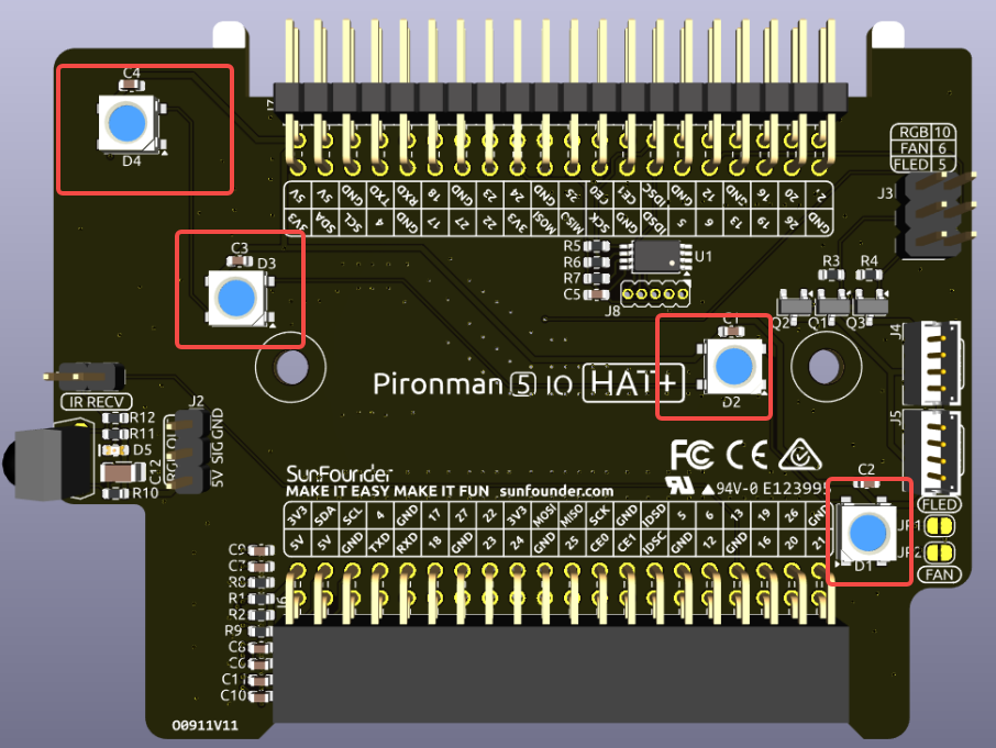
The board features 4 WS2812 RGB LEDs, offering customizable control. Users can turn them on or off, change the color, adjust the brightness, switch display modes, and set the speed of changes.
To modify the on and off state of the RGB LEDs,
trueto turn on the RGB LEDs,falseto turn them off.
sudo pironman5 -re true
To change their color, input the desired hexadecimal color values, such as
fe1a1a.
sudo pironman5 -rc fe1a1a
To change the brightness of the RGB LED (range: 0 ~ 100%):
sudo pironman5 -rb 100
To switch RGB LED display modes, choose from options:
solid/breathing/flow/flow_reverse/rainbow/rainbow_reverse/hue_cycle:
Note
If you set the RGB LED display mode to rainbow, rainbow_reverse, or hue_cycle, you will not be able to set the color using pironman5 -rc.
sudo pironman5 -rs breathing
To modify the speed of change (range: 0 ~ 100%):
sudo pironman5 -rp 80
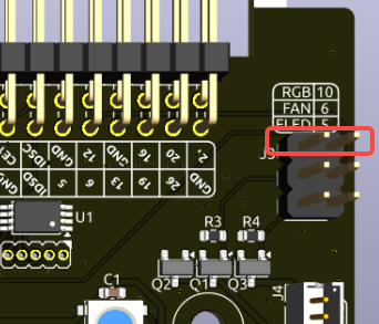
RGB Control Pin
The RGB LED is driven by SPI and connected to GPIO10, which is also the SPI MOSI pin. The two pins shown are used to connect the RGB to GPIO10. If not needed, the jumper can be removed.
RGB OUT Pins

The WS2812 RGB LEDs support serial connection, allowing for the attachment of an external RGB LED strip. Connect the SIG pin to the external strip’s DIN pin for expansion.
The default setup includes 4 RGB LEDs. Connect additional LEDs and update the count using:
sudo pironman5 --rgb-led-count [quantity]
Example:
sudo pironman5 --rgb-led-count 12
OLED Screen Connector
The OLED screen connector, with an address of 0x3C, is a key feature.

If the OLED Screen is not displaying or displaying incorrectly, you can follow these steps to troubleshoot the issue:
Check if the FPC cable of the OLED Screen is properly connected.
Use the following command to view the program’s run logs and check for error messages.
cat /var/log/pironman5/pironman5.logAlternatively, use the following command to check if the OLED’s i2c address 0x3C is recognized:
sudo i2cdetect -y 1
If the first two steps don’t reveal any issues, try restarting the pironman5 service to see if that resolves the problem.
sudo systemctl restart pironman5.service
Wake-Up Trigger

The onboard vibration switch is used to wake up the OLED display from sleep mode. When a vibration is detected, it sends a signal to reactivate the OLED, allowing the display to remain off when idle and wake automatically when motion is sensed.
If you remove the jumper cap labeled for the vibration switch, the wake-up function will be disabled. Once the OLED enters sleep mode, it will no longer be able to wake up. This option is intended for advanced users who wish to repurpose the corresponding GPIO pin for other applications.
Note
Jumper installed: Vibration wake-up is enabled.
Jumper removed: OLED cannot be woken once it turns off. The pin is freed for other uses.
Infrared Receiver
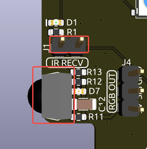
Model: IRM-56384, operating at 38KHz.
Connection: The IR receiver connects to GPIO13.
D1: An infrared reception indicator that blinks upon signal detection.
J8: A pin for enabling the infrared function. By default, a jumper cap is inserted for immediate functionality. Remove the cap to free GPIO13 if the IR receiver is not in use.
To utilize the IR receiver, verify its connection and install the necessary module:
Test the connection:
sudo ls /dev |grep lirc
Install the
lircmodule:sudo apt-get install lirc -y
Now, test the IR Receiver by running the following command.
mode2 -d /dev/lirc0
After running the command, press a button on the remote control, and the code of that button will be printed.
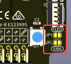
RGB Fan Pins
The IO expansion board supports up to two 5V non-CPU Fans. Both fans are controlled together.
J4 and J5 are two sets of fan ports. You need to connect the fans here.
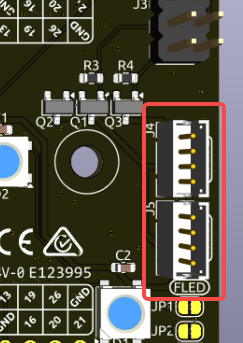
There are two sets of 2-pin connectors and two jumpers used to control the GPIO Fans and their LEDs. By default, the jumpers are connected to these pins, allowing control of the fans and LEDs via GPIO6 and GPIO5. If fan operation is not required, these jumpers can be removed to free up GPIO5 and GPIO6.
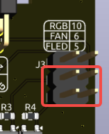
After removing the jumper caps, the fan or fan LED will default to being off. If activation is required, the two pads below can be bridged with solder. Once connected, the fan/LED will turn on when the system powers up and turn off when the system is powered down, but cannot be controlled via the IO port.
For instance, if set to 1: Performance mode, the GPIO Fans will activate at 50°C.
sudo pironman5 -gm 3
4: Quiet: The GPIO Fans will activate at 70°C.
3: Balanced: The GPIO Fans will activate at 67.5°C.
2: Cool: The GPIO Fans will activate at 60°C.
1: Performance: The GPIO Fans will activate at 50°C.
0: Always On: The GPIO Fans will always on.
If you connect the control pin of the RGB fan to different pins on the Raspberry Pi, you can use the following command to change the pin number.
sudo pironman5 -gp 18
Pin Headers

Two right-angle header connectors extend the Raspberry Pi’s GPIO, but note that the IR receiver, RGB LED, and fan occupy some pins. Remove the corresponding jumper caps to utilize these pins for other functions.
Pironman 5 MAX |
Raspberry Pi 5 |
|---|---|
IR Receiver(Optional) |
GPIO13 |
OLED SDA |
SDA |
OLED SCL |
SCL |
FAN(Optional) |
GPIO6 |
FLED(Optional) |
GPIO5 |
RGB(Optional) |
GPIO10 |