Note
Hello, welcome to the SunFounder Raspberry Pi & Arduino & ESP32 Enthusiasts Community on Facebook! Dive deeper into Raspberry Pi, Arduino, and ESP32 with fellow enthusiasts.
Why Join?
Expert Support: Solve post-sale issues and technical challenges with help from our community and team.
Learn & Share: Exchange tips and tutorials to enhance your skills.
Exclusive Previews: Get early access to new product announcements and sneak peeks.
Special Discounts: Enjoy exclusive discounts on our newest products.
Festive Promotions and Giveaways: Take part in giveaways and holiday promotions.
👉 Ready to explore and create with us? Click [here] and join today!
1.3 Quick Guide on PictoBlox
Required Components
In this project, we need the following components.
It’s definitely convenient to buy a whole kit, here’s the link:
Name |
ITEMS IN THIS KIT |
LINK |
|---|---|---|
ESP32 Starter Kit |
320+ |
You can also buy them separately from the links below.
COMPONENT INTRODUCTION |
PURCHASE LINK |
|---|---|
Now let’s learn how to use PictoBlox in two modes.
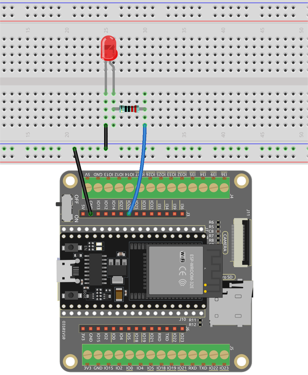
Also build a simple circuit to make this LED blink in 2 different modes.
Stage Mode
1. Connect to ESP32 Board
Connect your ESP32 board to the computer with a USB cable, usually the computer will automatically recognize your board and finally assign a COM port.
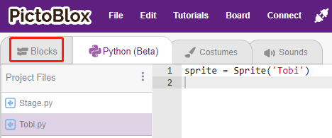
Open PictoBlox, the Python programming interface will open by default. And we need to switch to the Blocks interface.
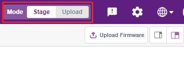
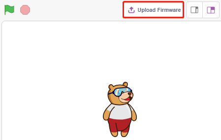
Then you will see the top right corner for mode switching. The default is Stage mode, where Tobi is standing on the stage.
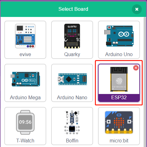
Click Board in the upper right navigation bar to select the board.
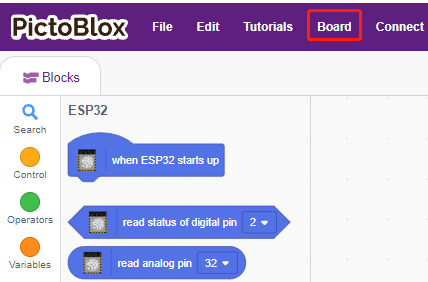
For example, choose ESP32.
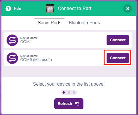
A connection window will then pop up for you to select the port to connect to, and return to the home page when the connection is complete. If you break the connection during use, you can also click Connect to reconnect.
Note
If it shows COM1 or no port, your computer may not recognize the board. See Manually Install Driver for ESP32.
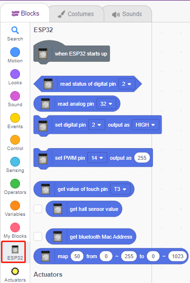
At the same time, ESP32 related palettes, such as ESP32, Actuators, etc., will appear in the Block Palette.
2. Upload Firmware
Since we’re going to work in the Stage mode, we must upload the firmware to the board. It will ensure real-time communication between the board and the computer. Uploading the firmware it is a one-time process. To do so, click on the Upload Firmware button.
After waiting for a while, the upload success message will appear.
Note
If you are using this board in PictoBlox for the first time, or if this board was previously uploaded with the Arduino IDE. Then you need to tap Upload Firmware before you can use it.
3. Programming
Open and run the script directly
Of course, you can open the scripts directly to run them, but please download them from github first.
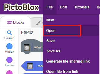
You can click on File in the top right corner and then choose Open.
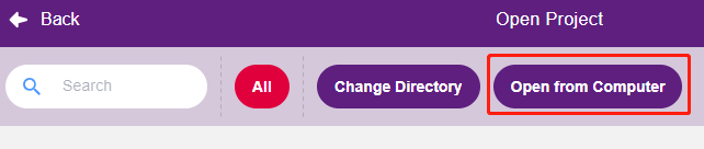
Choose Open from Computer.
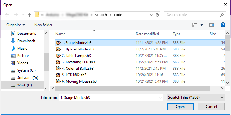
Then go to the path of esp32-starter-kit-main\scratch, and open 1. Stage Mode.sb3. Please ensure that you have downloaded the required code from github.
Click directly on the script to run it, some projects are click on the green flag or click on the sprite.
Program step by step
You can also write the script step by step by following these steps.
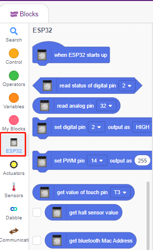
Click on the ESP32 palette.
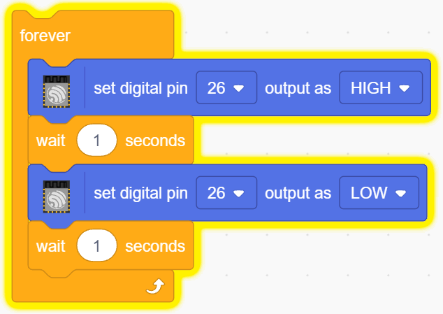
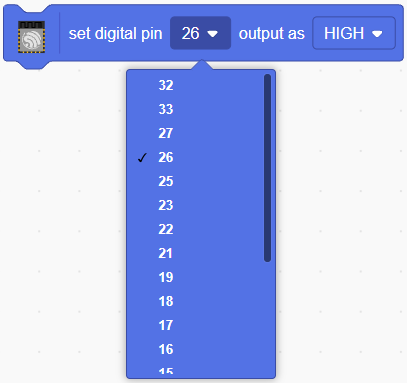
The LED is controlled by the digital pin 26 (only 2 states, HIGH or LOW), so drag the [set digital pin out as] block to the script area.
Since the default state of the LED is lit, now set pin 23 to LOW and click on this block and you will see the LED go off.
[set digital pin out as]: Set the digital pin to (HIGH/LOW) level.
In order to see the effect of continuous blinking LED, you need to use the [Wait 1 seconds] and [forever] blocks in the Control palette. Click on these blocks after writing, there is a yellow halo means it is running.
[Wait 1 seconds]: from the Control palette, used to set the time interval between 2 blocks.
[forever]: from the Control palette, allows the script to keep running unless manually paused.
Upload Mode
1. Connect to ESP32 Board
Connect your ESP32 board to the computer with a USB cable, usually the computer will automatically recognize your board and finally assign a COM port.
Open PictoBlox and click Board in the top right navigation bar to select the board.
For example, choose ESP32.
A connection window will then pop up for you to select the port to connect to, and return to the home page when the connection is complete. If you break the connection during use, you can also click Connect to reconnect.
Note
If it shows COM1 or no port, your computer may not recognize the board. See Manually Install Driver for ESP32.
At the same time, ESP32 related palettes, such as ESP32, Actuators, etc., will appear in the Block Palette.
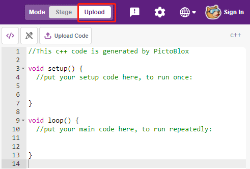
After selecting Upload mode, the stage will switch to the original code area.
2. Programming
Open and run the script directly
You can click on File in the top right corner.
Choose Open from Computer.
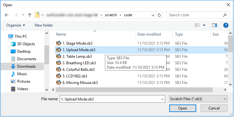
Then go to the path of esp32-starter-kit-main\scratch, and open 1. Upload Mode.sb3. Please ensure that you have downloaded the required code from github.
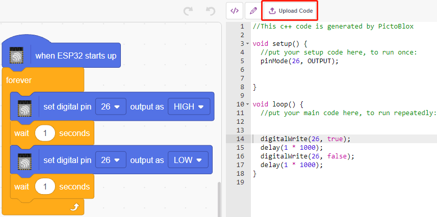
Finally, click the Upload Code button.
Program step by step
You can also write the script step by step by following these steps.
Click on the ESP32 palette.
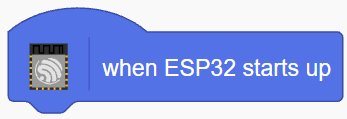
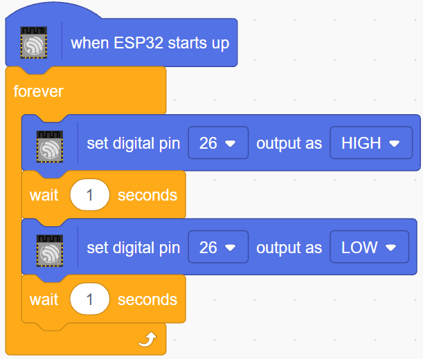
Drag [when ESP32 starts up] to the script area, which is required for every script.
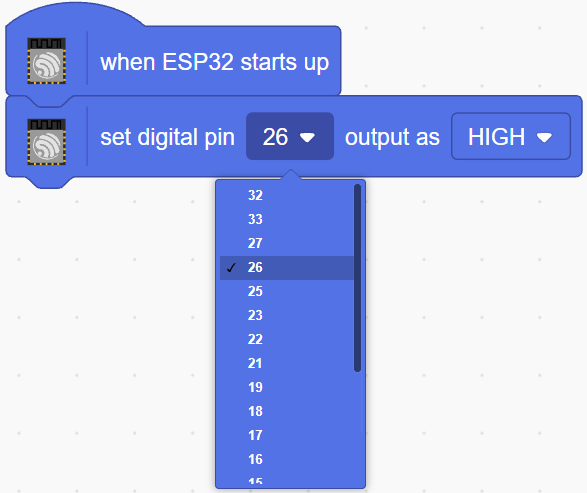
The LED is controlled by the digital pin26 (only 2 states HIGH or LOW), so drag the [set digital pin out as] block to the script area.
Since the default state of the LED is lit, now set pin26 to LOW and click on this block and you will see the LED go off.
[set digital pin out as]: Set the digital pin to (HIGH/LOW) level.
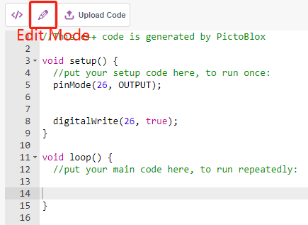
At this point you will see the code appear on the right side, if you want to edit this code, then you can turn Edit mode on.
In order to see the effect of continuous blinking LED, you need to use the [Wait 1 seconds] and [forever] blocks in the Control palette. Click on these blocks after writing, there is a yellow halo means it is running.
[Wait 1 seconds]: from the Control palette, used to set the time interval between 2 blocks.
[forever]: from the Control palette, allows the script to keep running unless the power is off.
Finally, click the Upload Code button.