Note
Hello, welcome to the SunFounder Raspberry Pi & Arduino & ESP32 Enthusiasts Community on Facebook! Dive deeper into Raspberry Pi, Arduino, and ESP32 with fellow enthusiasts.
Why Join?
Expert Support: Solve post-sale issues and technical challenges with help from our community and team.
Learn & Share: Exchange tips and tutorials to enhance your skills.
Exclusive Previews: Get early access to new product announcements and sneak peeks.
Special Discounts: Enjoy exclusive discounts on our newest products.
Festive Promotions and Giveaways: Take part in giveaways and holiday promotions.
👉 Ready to explore and create with us? Click [here] and join today!
6.1 Light-sensitive Array
A photoresistor or photocell is a light-controlled variable resistor. The resistance of a photoresistor decreases with increasing incident light intensity; in other words, it exhibits photoconductivity. A photoresistor can be applied in light-sensitive detector circuits, and light- and darkness-activated switching circuits.
The resistance of a photoresistor changes with incident light intensity. If the light intensity gets higher, the resistance decreases; if it gets lower, the resistance increases. In this experiment, we will use eight LEDs to show the light intensity. The higher the light intensity is, the more LEDs will light up. When the light intensity is high enough, all the LEDs will be on. When there is no light, all the LEDs will go out.
Required Components
In this project, we need the following components.
It’s definitely convenient to buy a whole kit, here’s the link:
Name |
ITEMS IN THIS KIT |
LINK |
|---|---|---|
3 in 1 Starter Kit |
380+ |
You can also buy them separately from the links below.
COMPONENT INTRODUCTION |
PURCHASE LINK |
|---|---|
Schematic
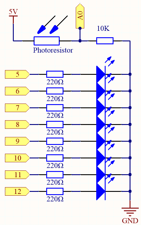
Wiring

Code
Note
Open the
6.1.light_control_led.inofile under the path of3in1-kit\basic_project\6.1.light_control_led.Or copy this code into Arduino IDE.
Or upload the code through the Arduino Web Editor.
Now, shine some light on the photoresistor, and you will see several LEDs light up. Shine more light and you will see more LEDs light up. When you place it in a dark environment, all the LEDs will go out.
How it works?
void loop()
{
    sensorValue = analogRead(photocellPin); //read the value of A0
    ledLevel = map(sensorValue, 300, 1023, 0, NbrLEDs); // map to the number of LEDs
    for (int led = 0; led < NbrLEDs; led++)//
    {
        if (led < ledLevel ) //When led is smaller than ledLevel, run the following code.
        {
            digitalWrite(ledPins[led], HIGH); // turn on pins less than the level
        }
        else
        {
            digitalWrite(ledPins[led],LOW); // turn off pins higher than
        }
    }
}
By using the map() function, you can map the photoresistor value to the 8 LEDs, for example, if sensorValue is 560, then ledLevel is 4, so at this point, ledPins[0] to ledPins[4] should be lit, and ledPins[5] to ledPins[7] should be off.