Hardware Introduction
The Robot Hat V4 features 2 lithium battery charging, 5V/3A DC-DC discharge, I2S audio output and speaker, a simple battery level indicator, microcontroller-based PWM and ADC drivers, as well as motor drivers.
Pinout
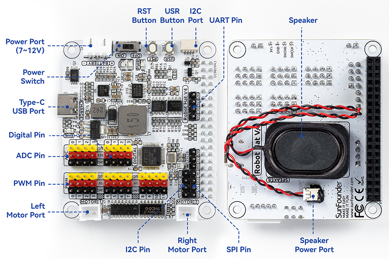
- Power Port
7-12V PH2.0 3pin power input.
Powering the Raspberry Pi and Robot HAT at the same time.
- Power Switch
Turn on/off the power of the robot HAT.
When you connect power to the power port, the Raspberry Pi will boot up. However, you will need to switch the power switch to ON to enable Robot HAT.
- Type-C USB Port
Insert the Type-C cable to charge the battery.
At the same time, the charging indicator lights up in red color.
When the battery is fully charged, the charging indicator turns off.
If the USB cable is still plugged in about 4 hours after it is fully charged, the charging indicator will blink to prompt.
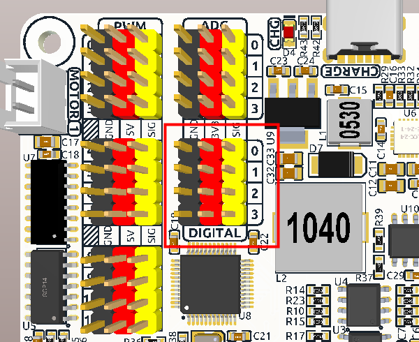
- Digital Pin
4-channel digital pins, D0-D3.
Pin: Digital IO.
API: class Pin.
- ADC Pin
- PWM Pin
- Left/Right Motor Port
2-channel XH2.54 motor ports.
Pin: Motor Port.
API: module motor,
1for left motor port,2for right motor port.
- I2C Pin and I2C Port
- SPI Pin
P2.54 7-pin SPI interface.
Pin: SPI.
- UART Pin
P2.54 4-pin interface.
Pin: UART.
- RST Button
- USR Button
- Battery Indicator
Two LEDs light up when the voltage is higher than 7.6V.
One LED lights up in the 7.15V to 7.6V range.
Below 7.15V, both LEDs turn off.
- Speaker and Speaker Port
Speaker: This is a 2030 audio chamber speaker.
Speaker Port: The Robot HAT is equipped with onboard I2S audio output, along with a 2030 audio chamber speaker, providing a mono sound output.
Pin: Speaker and Speaker Port.
API: class Music
Pin Mapping
Robot Hat V4 |
Raspberry Pi |
Robot Hat V4 |
Raspberry Pi |
|---|---|---|---|
NC |
3V3 |
5V |
5V |
SDA |
SDA |
5V |
5V |
SCL |
SCL |
GND |
GND |
D1 |
GPIO4 |
TXD |
TXD |
GND |
GND |
RXD |
RXD |
D0 |
GPIO17 |
I2S BCLK |
GPIO18 |
D2 |
GPIO27 |
GND |
GND |
D3 |
GPIO22 |
MOTOR 1 DIR |
GPIO23 |
NC |
3V3 |
MOTOR 2 DIR |
GPIO24 |
SPI MOSI |
MOSI |
GND |
GND |
SPI MISO |
MISO |
USR BUTTON |
GPIO25 |
SPI SCLK |
SCLK |
SPI CE0 |
CE0 |
GND |
GND |
NC |
CE1 |
NC |
ID_SD |
NC |
ID_SC |
MCU Reset |
GPIO5 |
GND |
GND |
(SPI)BSY |
GPIO6 |
Board Identifier 2 |
GPIO12 |
Board Identifier 1 |
GPIO13 |
GND |
GND |
I2S LRCLK |
GPIO19 |
RST BUTTON |
GPIO16 |
USER LED |
GPIO26 |
NC |
GPIO20 |
GND |
GND |
I2S SDATA |
GPIO21 |
Digital IO
Robot HAT has 4 sets of 3Pin digital pins.
Robot Hat V4 |
Raspberry Pi |
|---|---|
D0 |
GPIO17 |
D1 |
GPIO4 |
D2 |
GPIO27 |
D3 |
GPIO22 |
ADC
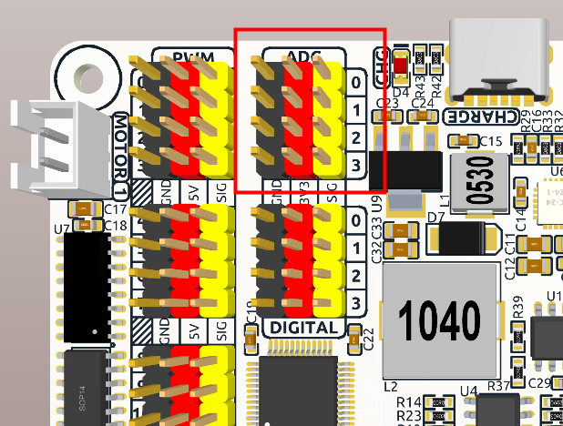
The Robot HAT features four sets of 3Pin ADC (Analog to Digital Converter) pins, each spaced 2.54mm apart. These pins operate at a 3.3V power supply. The ADC function, offering 12-bit precision, is facilitated by an onboard microcontroller. Detailed instructions for reading ADC values are provided in the On-Board MCU section.
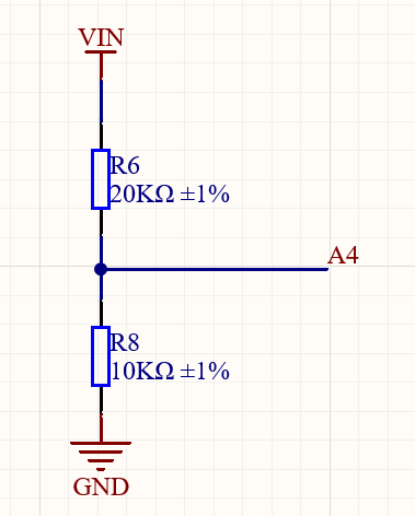
Also, ADC channel A4 is connected to the battery through a voltage divider using resistors, which will be used to measure the battery voltage to estimate the approximate battery charge.
The voltage divider ratio is 20K/10K, so:
A4 voltage (Va4) = value_A4 / 4095.0 * 3.3
Battery voltage (Vbat) = Va4*3
Battery voltage (Vbat) = value_A4 / 4095.0 * 3.3 * 3
PWM
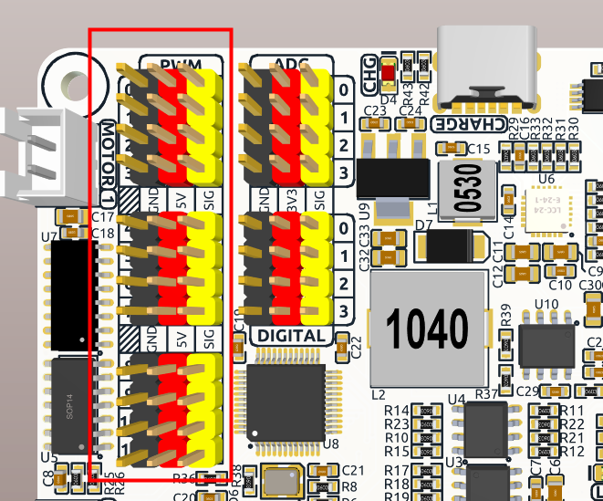
Robot HAT has 4 sets of 3Pin PWM pins, each spaced 2.54mm apart, and the power supply is 5V. The method of using the PWM is described in detail in On-Board MCU.
Note
PWM13 & 14 channels are used for motor drive.
I2C
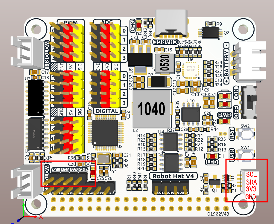
The Robot HAT has two I2C interfaces. One is the P2.54 4-pin interface, and the other is the SH1.0 4-pin interface, which is compatible with QWIIC and STEMMA QT. These I2C interfaces are connected to the Raspberry Pi’s I2C interface via GPIO2 (SDA) and GPIO3 (SCL). The board also features an On-Board MCU, and the two signal lines have 10K pull-up resistors.
SPI
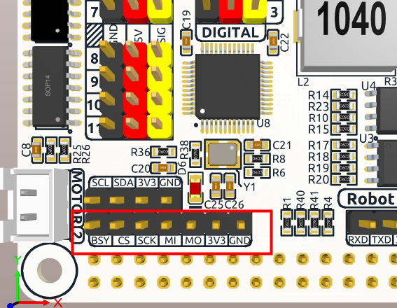
The SPI interface of the Robot HAT is a 7-pin P2.54 interface. It connects to the SPI interface of the Raspberry Pi and includes an additional I/O pin that can be used for purposes such as interrupts or resets.
Robot Hat V4 |
Raspberry Pi |
|---|---|
BSY |
GPIO6 |
CS |
CE0(GPIO8) |
SCK |
SCLK(GPIO11) |
MI |
MISO(GPIO9) |
MO |
MOSI(GPIO10) |
3V3 |
3.3V Power |
GND |
Ground |
UART
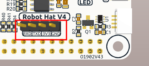
The UART interface of the Robot HAT is a 4-pin P2.54 interface. It connects to the Raspberry Pi’s GPIO14 (TXD) and GPIO15 (RXD) pins.
Speaker and Speaker Port
The Robot HAT is equipped with onboard I2S audio output, along with a 2030 audio chamber speaker, providing a mono sound output.
I2S |
Raspberry Pi |
|---|---|
LRCLK |
GPIO19 |
BCLK |
GPIO18 |
SDATA |
GPIO21 |
Motor Port
The motor driver of the Robot HAT supports 2 channels and can be controlled using 2 digital signals for direction and 2 PWM signals for speed control.
Motor |
IO |
|---|---|
Motor1 Dir |
GPIO23 |
Motor1 Power |
PWM13 |
Motor2 Dir |
GPIO24 |
Motor2 Power |
PWM12 |
Battery Level Indicator
The battery level indicator on the Robot HAT monitors the battery voltage using a voltage divider method and serves as a reference for estimating the battery level. The relationship between the LED and voltage is as follows:
LED Battery |
Total Voltage |
|---|---|
2 LEDs on |
Greater than 7.6V |
1 LED on |
Greater than 7.15V |
Both LEDs off |
Less than 7.15V |
When any one of the batteries reaches or exceeds 4.1V while the others are below that threshold, the charging current of that specific battery will be reduced.