Note
Hello, welcome to the SunFounder Raspberry Pi & Arduino & ESP32 Enthusiasts Community on Facebook! Dive deeper into Raspberry Pi, Arduino, and ESP32 with fellow enthusiasts.
Why Join?
Expert Support: Solve post-sale issues and technical challenges with help from our community and team.
Learn & Share: Exchange tips and tutorials to enhance your skills.
Exclusive Previews: Get early access to new product announcements and sneak peeks.
Special Discounts: Enjoy exclusive discounts on our newest products.
Festive Promotions and Giveaways: Take part in giveaways and holiday promotions.
👉 Ready to explore and create with us? Click [here] and join today!
2.2.6 Speed Sensor Module
Introduction
In this project, we will learn the use of the speed sensor module. A Speed sensor module is a type of tachometer that is used to measure the speed of a rotating object like a motor.
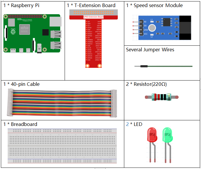
Required Components
In this project, we need the following components.
It’s definitely convenient to buy a whole kit, here’s the link:
Name |
ITEMS IN THIS KIT |
LINK |
|---|---|---|
Raphael Kit |
337 |
You can also buy them separately from the links below.
COMPONENT INTRODUCTION |
PURCHASE LINK |
|---|---|
- |
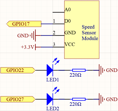
Schematic Diagram
Experimental Procedures
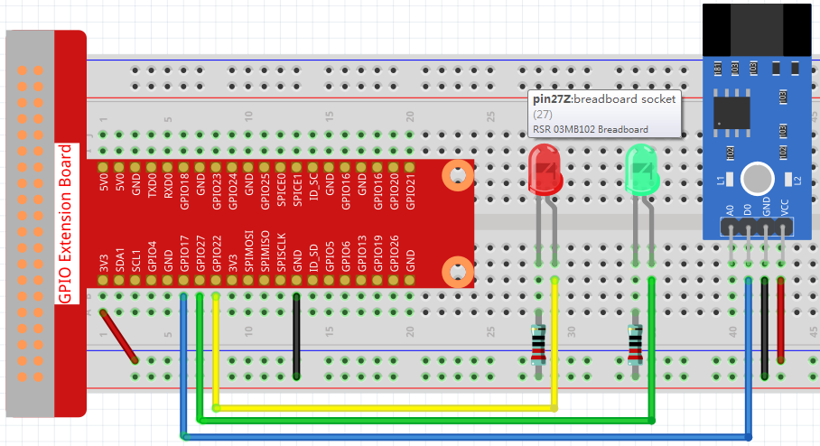
Step 1: Build the circuit.
Step 2: Change directory.
cd ~/raphael-kit/python
Step 3: Run.
sudo python3 2.2.6_speed_sensor_module.py
After the code runs, the green LED will light up. If you place an obstacle in the gap of the speed sensor module, the “light blocked” will be printed on the screen and the red LED will be lit. Remove the obstacle and the green LED will light up again.
Code
Note
You can Modify/Reset/Copy/Run/Stop the code below. But before that, you need to go to source code path like raphael-kit/python. After modifying the code, you can run it directly to see the effect.
#!/usr/bin/env python3
import RPi.GPIO as GPIO

speedPin  = 17
Gpin   = 27
Rpin   = 22

def setup():
    GPIO.setmode(GPIO.BCM)       #
    GPIO.setup(Gpin, GPIO.OUT)     # Set Green Led Pin mode to output
    GPIO.setup(Rpin, GPIO.OUT)     # Set Red Led Pin mode to output
    GPIO.setup(speedPin, GPIO.IN, pull_up_down=GPIO.PUD_UP)    # Set speedPin's mode is input, and pull up to high level(3.3V)
    GPIO.add_event_detect(speedPin, GPIO.BOTH, callback=detect, bouncetime=200)

def Led(x):
    if x == 0:
        GPIO.output(Rpin, 0)
        GPIO.output(Gpin, 1)
    if x == 1:
        GPIO.output(Rpin, 1)
        GPIO.output(Gpin, 0)
        print ('Light was blocked')

def detect(chn):
    Led(GPIO.input(speedPin))

def loop():
    while True:
        pass

def destroy():
    GPIO.output(Gpin, GPIO.LOW)       # Green led off
    GPIO.output(Rpin, GPIO.LOW)       # Red led off
    GPIO.cleanup()                     # Release resource

if __name__ == '__main__':     # Program start from here
    setup()
    try:
        loop()
    except KeyboardInterrupt:  # When 'Ctrl+C' is pressed, the child program destroy() will be  executed.
        destroy()
Code Explanation
GPIO.add_event_detect(speedPin, GPIO.BOTH, callback=detect, bouncetime=200)
Add an event here, triggered by a change in the level of speedPin and call detect() to control the 2 LEDs on and off.
def Led(x):
    if x == 0:
        GPIO.output(Rpin, 0)
        GPIO.output(Gpin, 1)
    if x == 1:
        GPIO.output(Rpin, 1)
        GPIO.output(Gpin, 0)
        print ('Light was blocked')
Define a function Led() that turns the red LED on and prints Light was blocked when the parameter is 1; turn the green LED on when the parameter is 0.
def detect(chn):
    Led(GPIO.input(speedPin))
Define a callback function where the value of speedPin will control the turning on or off of the 2 LEDs.
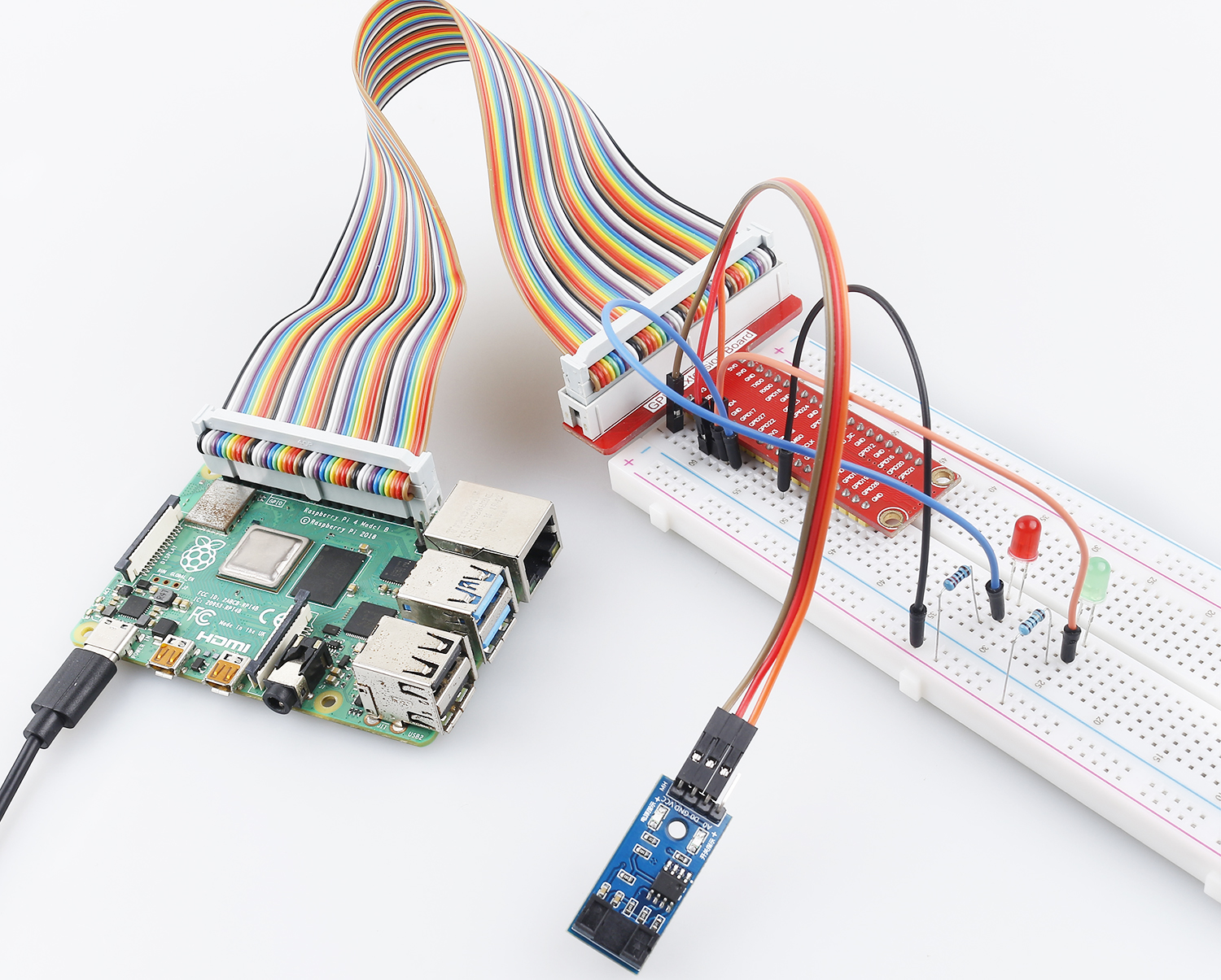
Phenomenon Picture