Note
Hello, welcome to the SunFounder Raspberry Pi & Arduino & ESP32 Enthusiasts Community on Facebook! Dive deeper into Raspberry Pi, Arduino, and ESP32 with fellow enthusiasts.
Why Join?
Expert Support: Solve post-sale issues and technical challenges with help from our community and team.
Learn & Share: Exchange tips and tutorials to enhance your skills.
Exclusive Previews: Get early access to new product announcements and sneak peeks.
Special Discounts: Enjoy exclusive discounts on our newest products.
Festive Promotions and Giveaways: Take part in giveaways and holiday promotions.
👉 Ready to explore and create with us? Click [here] and join today!
1.2.1 Active Buzzer
Introduction
In this project, we will learn how to drive an active buzzer to beep with a PNP transistor.
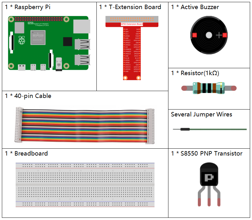
Required Components
In this project, we need the following components.
It’s definitely convenient to buy a whole kit, here’s the link:
Name |
ITEMS IN THIS KIT |
LINK |
|---|---|---|
Raphael Kit |
337 |
You can also buy them separately from the links below.
COMPONENT INTRODUCTION |
PURCHASE LINK |
|---|---|
- |
|
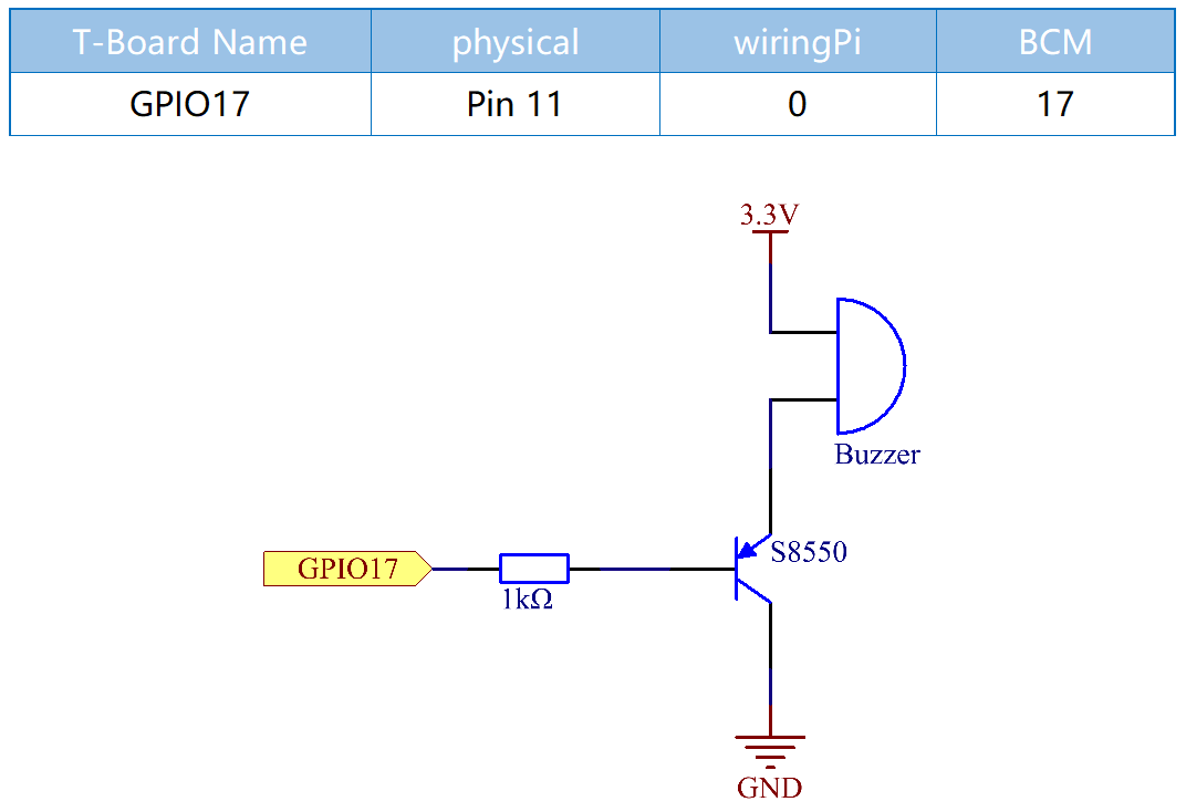
Schematic Diagram
In this experiment, an active buzzer, a PNP transistor and a 1k resistor are used between the base of the transistor and GPIO to protect the transistor. When the GPIO17 of Raspberry Pi output is supplied with low level (0V) by programming, the transistor will conduct because of current saturation and the buzzer will make sounds. But when high level is supplied to the IO of Raspberry Pi, the transistor will be cut off and the buzzer will not make sounds.
Experimental Procedures
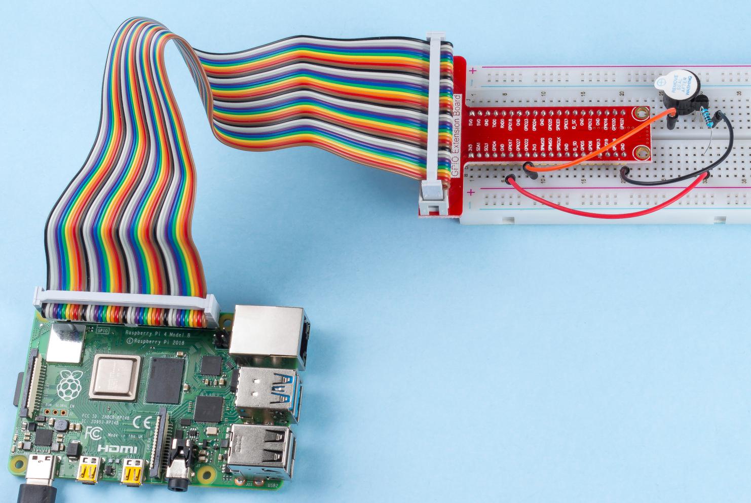
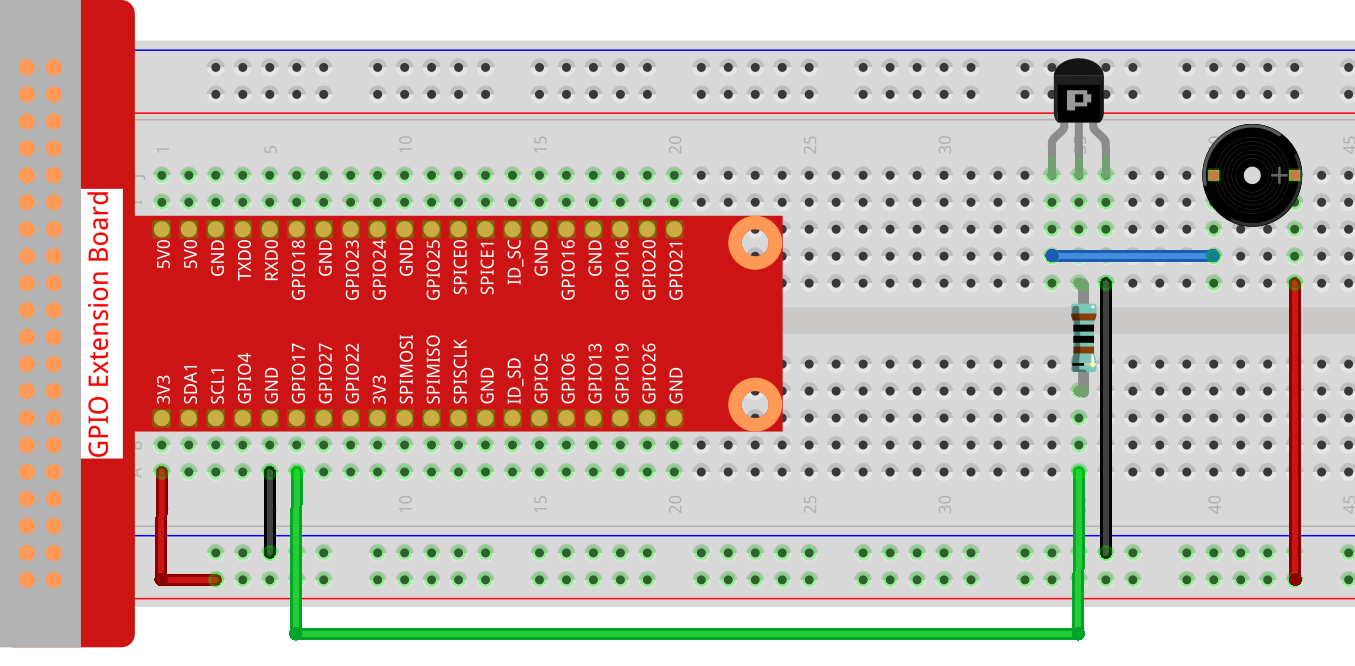
Step 1: Build the circuit. (The active buzzer has a white table sticker on the surface and a black back.)
Step 2: Go to the folder of the code.
cd ~/raphael-kit/nodejs/
Step 3: Run.
sudo node active_buzzer.js
The code run, the buzzer beeps.
Code
const Gpio = require('pigpio').Gpio;
const active = new Gpio(17,{mode: Gpio.OUTPUT});

setInterval(() => {
  active.digitalWrite(!active.digitalRead());
}, 500);

process.on('SIGINT',function(){
  active.digitalWrite(1);
  process.exit();
});
Code Explanation
const Gpio = require('pigpio').Gpio;
const active = new Gpio(17,{mode: Gpio.OUTPUT});
Import the pigpio module, and instantiate an object active to control the IO port Gpio17, and the mode is set to output mode.
setInterval(() => {
  active.digitalWrite(!active.digitalRead());
}, 500);
The active buzzer is similar to the LED in usage and can be controlled with digitalWrite(), and digitalRead() is used to read the current pin level.
Here we make the active buzzer change its working state every 500ms.
process.on('SIGINT', function() {
    /* DO SOME STUFF HERE */

    process.exit()
})
Handle Ctrl+C, here is used to stop the buzzer sounding when exiting the program.
Phenomenon Picture