Note
Hello, welcome to the SunFounder Raspberry Pi & Arduino & ESP32 Enthusiasts Community on Facebook! Dive deeper into Raspberry Pi, Arduino, and ESP32 with fellow enthusiasts.
Why Join?
Expert Support: Solve post-sale issues and technical challenges with help from our community and team.
Learn & Share: Exchange tips and tutorials to enhance your skills.
Exclusive Previews: Get early access to new product announcements and sneak peeks.
Special Discounts: Enjoy exclusive discounts on our newest products.
Festive Promotions and Giveaways: Take part in giveaways and holiday promotions.
👉 Ready to explore and create with us? Click [here] and join today!
2.1.7 Potentiometer(MCP3008)
Note

Depending on your kit version, please identify whether you have ADC0834 or MCP3008 and proceed with the matching section.
Introduction
The ADC function is used to convert analog signals into digital values. In this experiment, we use the MCP3008 ADC chip to perform this conversion. A potentiometer is used to generate a variable voltage, which changes the physical quantity. The MCP3008 then converts this analog voltage into a digital value that can be read and processed by the Raspberry Pi.
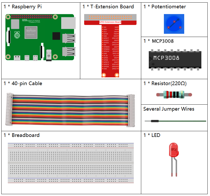
Required Components
In this project, we need the following components.
It’s definitely convenient to buy a whole kit, here’s the link:
Name |
ITEMS IN THIS KIT |
LINK |
|---|---|---|
Raphael Kit |
337 |
You can also buy them separately from the links below.
COMPONENT INTRODUCTION |
PURCHASE LINK |
|---|---|
- |
Schematic Diagram
T-Board Name |
physical |
WiringPi |
BCM |
|---|---|---|---|
SPICE0 |
pin24 |
10 |
8 |
SPIMOSI |
pin19 |
12 |
10 |
SPIMISO |
pin21 |
13 |
9 |
SPISCLK |
pin23 |
14 |
11 |
GPIO22 |
pin15 |
3 |
22 |

Experimental Procedures
Step 1: Build the circuit.
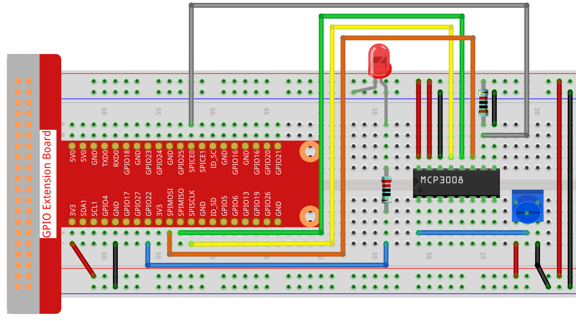
Note
Please place the chip by referring to the corresponding position depicted in the picture. Note that the grooves on the chip should be on the left when it is placed.
Step 2: Open the code file.
cd ~/raphael-kit/c/2.1.7-2/
Step 3: Compile the code.
gcc 2.1.7_Potentiometer.c -lwiringPi
Step 4: Run.
sudo ./a.out
After the code runs, rotate the knob on the potentiometer, the intensity of LED will change accordingly.
Note
If it does not work after running, or there is an error prompt: "wiringPi.h: No such file or directory", please refer to Install and Check the WiringPi.
Code
#include <wiringPi.h>
#include <wiringPiSPI.h>
#include <stdio.h>
#include <softPwm.h>

#define SPI_CHANNEL 0  // CE0
#define SPI_SPEED   1000000  // 1MHz
#define LedPin      3

int readADC(int channel) {
    if (channel < 0 || channel > 7) return -1;

    unsigned char buffer[3];
    buffer[0] = 1;                             // Start bit
    buffer[1] = (8 + channel) << 4;            // Single-ended mode, channel
    buffer[2] = 0;

    wiringPiSPIDataRW(SPI_CHANNEL, buffer, 3);

    int value = ((buffer[1] & 3) << 8) | buffer[2];
    return value;
}

int main(void) {
    if (wiringPiSetup() == -1) {
        printf("WiringPi init failed!\n");
        return 1;
    }

    if (wiringPiSPISetup(SPI_CHANNEL, SPI_SPEED) == -1) {
        printf("SPI setup failed!\n");
        return 1;
    }

    softPwmCreate(LedPin, 0, 100);

    while (1) {
        int analogVal = readADC(0);  // CH0
        printf("ADC Value: %d\n", analogVal);

        int pwmVal = analogVal * 100 / 1023;  // Normalize to 0–100
        softPwmWrite(LedPin, pwmVal);

        delay(100);
    }

    return 0;
}
Code Explanation
#define SPI_CHANNEL 0  // CE0
#define SPI_SPEED   1000000  // 1MHz
#define LedPin      3
Define the SPI channel as CE0 (chip enable 0), set the SPI speed to 1MHz, and assign GPIO3 to the LED pin.
int readADC(int channel) {
    if (channel < 0 || channel > 7) return -1;

    unsigned char buffer[3];
    buffer[0] = 1;                             // Start bit
    buffer[1] = (8 + channel) << 4;            // Single-ended mode, channel
    buffer[2] = 0;

    wiringPiSPIDataRW(SPI_CHANNEL, buffer, 3);

    int value = ((buffer[1] & 3) << 8) | buffer[2];
    return value;
}
This function is used to read analog data from MCP3008.
First, it checks if the channel number is within the valid range (0 to 7).
It initializes a 3-byte array, where:
buffer[0] = 1: Start bit for MCP3008 communication.buffer[1] = (8 + channel) << 4: Constructs the configuration byte for single-ended mode and selects the desired channel.buffer[2] = 0: Placeholder byte to receive the result.
wiringPiSPIDataRWsends and receives data through the SPI channel.The return value is extracted from the last two bytes using bitwise operations to obtain a 10-bit ADC result.
int main(void) {
    if (wiringPiSetup() == -1) {
        printf("WiringPi init failed!\n");
        return 1;
    }

    if (wiringPiSPISetup(SPI_CHANNEL, SPI_SPEED) == -1) {
        printf("SPI setup failed!\n");
        return 1;
    }

    softPwmCreate(LedPin, 0, 100);

    while (1) {
        int analogVal = readADC(0);  // CH0
        printf("ADC Value: %d\n", analogVal);

        int pwmVal = analogVal * 100 / 1023;  // Normalize to 0–100
        softPwmWrite(LedPin, pwmVal);

        delay(100);
    }

    return 0;
}
In the main function:
wiringPiSetup()initializes the WiringPi library.wiringPiSPISetup()initializes SPI communication on channel 0 at 1MHz.softPwmCreate()sets up software PWM on GPIO3 with an initial duty cycle of 0 and a range of 0–100.
The program enters an infinite loop where:
It reads the ADC value from channel 0 (connected to a potentiometer).
Prints the ADC value to the terminal.
Converts the 10-bit ADC value to a PWM duty cycle between 0 and 100.
Writes the PWM value to the LED, so the brightness reflects the potentiometer’s position.
delay(100) pauses for 100 milliseconds before the next read/write cycle.