PiPower 5 HAT
Interface Overview

USB Type-C Power Input
External power input for supplying the Raspberry Pi and charging the battery simultaneously.
Supports USB Power Delivery (PD) protocol, input range 5V–15V.
Power Input Selector (DIP Switch)
Allows selection of different input power profiles for flexible configuration.
Default ON Jumper
Defines whether the system should automatically power on when external power is connected while the device is shut down.
ON = Auto power-on enabled, OFF = Manual start required.
SDSIG (Shutdown Signal)
Provides shutdown detection for Raspberry Pi.
When bridged to PI3V3, it works with Raspberry Pi 4 and Pi 5.
When shorted to Pin 26, it supports Pi 3 and Pi Zero.
After proper configuration, PiPower5 will cut power automatically once the Raspberry Pi shuts down.
PWR LED (Output Status Indicator)
Lights up when the system output is active.
BAT LED (Battery Status Indicator)
Lights up when the system is powered by the battery.
A reminder to monitor battery consumption when running without external power.
Power Button
Single press: Enable output power.
Long press (2 seconds): Sends a safe shutdown request via I²C.
Long press (5 seconds): Forces an immediate power-off (hard shutdown).
Customizable: Single and double-press actions can be reconfigured by software.
External Power Button Terminal (ZH1.5 2P)
Allows connection of an external physical power button.
External Power Button Header (2.54mm)
An alternative solderable header option for external power button connection.
Battery Indicator LEDs
Display remaining battery capacity and charging status.
Note: Even when the system is off, LEDs remain active during charging until the battery is fully charged.
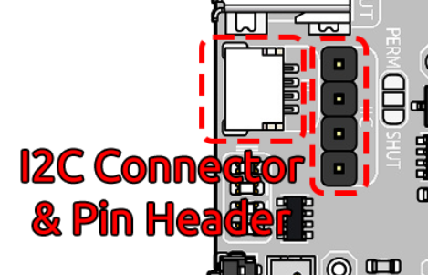
I²C Interface (SH1.0 4P)
Compatible with Qwiic and STEMMA QT ecosystems.
Used for communication with the onboard microcontroller and external peripherals.
I²C Interface (1x4P 2.54mm Header)
Alternative I²C breakout with 3V3 power output, configurable as always-on or switched.
I²C Power Selection Jumper
PERM: 3V3 power is always on when external power is connected.
SHUT (default): 3V3 power cuts off automatically when the system shuts down.
USB Type-A Output Port
Provides regulated 5V output, suitable for powering peripherals or other devices.
When powering a Raspberry Pi, you may encounter a non-PD power supply warning, which can be safely ignored.
2x4P 2.54mm Power Output Header
Additional 5V output for external modules or SBCs.
Raspberry Pi GPIO Header (Female Connector)
Direct interface for Raspberry Pi, passing through power, I²C, and other signals.
Fully compatible with Raspberry Pi pinout.
Raspberry Pi GPIO Header (Male Pin Breakout)
Brings Raspberry Pi GPIO pins out for stacking HATs or external expansion.
Note: I²C lines and Pin 26 are already occupied by PiPower5 functions.
You can also connect a GPIO extension cable (from the bottom of the side panel) to experiment on a breadboard.
Battery Connector (XH2.54 3P)
Battery connection interface.
Pin order (left to right): Negative, Mid-point (between two cells), Positive.
Designed for 7.4V (2-cell) Li-ion/LiPo batteries.
Reverse Battery Warning LEDs
Two red LEDs light up if the battery is connected in reverse polarity, warning of incorrect installation.
Screw Terminals for Battery & Input Power
Alternative connection method for external batteries and power sources.
Supports 5V–15V external input (recommended: >9V).
Battery support: 2 x 3.7V Li-ion / LiPo cells only (NOT compatible with LiFePO₄ batteries).
Specification Table
Parameter |
Minimum |
Typical |
Maximum |
Unit |
|---|---|---|---|---|
Battery Shutdown Current |
- |
60 |
- |
µA |
Battery Quiescent Current |
- |
25 |
- |
mA |
DC-DC Output Voltage |
5.1957 |
5.2855 |
5.3766 |
V |
DC-DC Over-Temperature Protection |
- |
150 |
- |
℃ |
Battery Charging Power |
- |
- |
20 |
W |
Charging Over-Temperature Protection |
- |
125 |
- |
℃ |
Balancing Resistor |
- |
60 |
- |
Ω |
Balancing Activation Voltage |
- |
4.2 |
- |
V |
Power Input

When using Raspberry Pi 5, it is recommended to use a USB PD power supply or a DC power supply with a minimum output of 32W. Otherwise, during periods of high power consumption, the battery may fail to charge properly or even deplete its charge due to insufficient power supply.
You can monitor the BAT LED indicator to check the battery status. When external power is sufficient, the BAT LED should remain off, indicating that the battery is in standby mode and not being discharged. If the BAT LED lights up, it means the battery is supplying power to the device, possibly due to insufficient or disconnected external power. Prolonged illumination of the BAT LED may lead to excessive battery discharge, preventing it from functioning as an uninterrupted power supply (UPS) during power outages. Ensure you are using a power source that meets the required specifications to avoid such scenarios.

Power Path
The PiPower 5 integrates power path management, enabling automatic power source switching to minimize battery wear and ensure uninterrupted power supply. The key functionalities include:
When an external power source is connected, the 5V output is supplied via a step-down circuit from the external source. The output can be turned off using a switch. If conditions allow, the external power source can also charge the battery simultaneously (see the “Charging Current” section for details).
Upon disconnection of the external power source, the system immediately switches to battery power via a step-down circuit. This seamless transition ensures the system continues functioning normally during power interruptions.
You can check the BAT LED indicator to confirm whether the battery is currently powering the system.
Charging Current
The charging current is subject to two types of limitations:
Note
The charging current is determined by both the “Screw Terminal Power Charging Limitation” and the “Charge Power Selection Limitation” and is constrained by the smaller value between the two.
Screw Terminal Power Charging Limitation
When supplying power via screw terminal power input, the charging current is automatically adjusted based on the input voltage, as shown below:
Input Voltage (VBUS)
Maximum Charging Current
4.5 < VBUS ≤ 6.5V
3A
6.5 < VBUS ≤ 9.5V
2A
9.5 < VBUS ≤ 13.5V
1.5A
13.5 < VBUS ≤ 16.5V
2A
Charge Power Selection Limitation
A 2-position DIP switch on the board allows selection of different charge power levels. The corresponding allocation of charging power and output power for each setting is as follows:

Charge Sel 1
Charge Sel 2
Charging Power
0
0
5W
1
0
10W
0
1
15W
1
1
20W
How to choose the charging power
The formula is:
Power supply capacity = Raspberry Pi required power + Charging power
We recommend estimating the Raspberry Pi’s power requirement at 20W to 25W.
If you use a 30W power supply, set charging power to 10W or 5W.
If you use a 45W power supply, you can safely set charging power to 20W.
If you are familiar with your Raspberry Pi’s power needs, you may set a higher charging power as long as you reserve enough margin for occasional power spikes.
⚠️ Be cautious: insufficient power may cause the Raspberry Pi to shut down unexpectedly.
Charging Process
When the battery voltage
VBAT <= 2.5V, the system performs trickle charging at a low current, approximately 50 mA.When
2.5V < VBAT <= VTRKL, trickle charging continues, and the battery charging current increases to approximately 200 mA.When
VTRKL < VBAT < VCV, the system switches to constant current charging, supplying a preset constant current to the battery.Once
VBAT = VCV, and the battery voltage approaches the fully charged level, the charging current gradually decreases, transitioning to constant voltage charging.During constant voltage charging, when the charging current drops below
ISTOPand the battery voltage is near the constant voltage threshold, charging stops, and the battery enters a fully charged state.- In the fully charged state, the system continuously monitors the battery voltage. If the voltage falls belowVRCH, charging resumes automatically.
Protection Features
The PiPower 5 offers comprehensive protection features, including input undervoltage and overvoltage protection, as well as overheating protection for both the charging chip and DC-DC converter. These features ensure stable and reliable system operation.
Charge Balancing
The onboard charge-balancing chip activates a 60Ω resistor to discharge the battery at a low current when it detects that a single cell’s voltage exceeds 4.2V. This feature helps maintain voltage balance across cells.
Temperature Protection
The charging process is automatically halted when the internal temperature of the charging chip exceeds 125°C. Similarly, the DC-DC chip disables output when its internal temperature surpasses 150°C.
Power Button

Onboard power button for controlling the board’s power:
Single press: Activates output.
Hold for 2 seconds until the middle two battery LEDs light up, then release: Sends a shutdown request via I2C.
Hold for more than 5 seconds: Directly turns off output.
Battery Indicators
Four onboard LEDs indicate the battery level and charging status.
Note
If the device is charging during shutdown, the indicator light will continue to display the charging status until charging is complete.

4 LEDs lit: Battery >80%
3 LEDs lit: 60%< Battery <80%
2 LEDs lit: 40%< Battery <60%
1 LED lit: 20%< Battery <40%
First LED flashing: Battery <20%
LEDs light up sequentially in a cycle: Charging in progress
Middle two LEDs flashing: Waiting shutdown signal
All LEDs off: Unpowered or in sleep mode
Battery Connector
VH3.96 2P battery connector and screw terminal battery connector.

External Power Button Terminal & Header
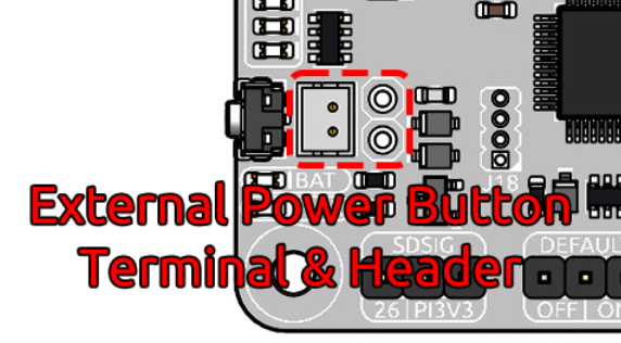
This terminal or header is designed for connecting an external power button. Connect a momentary switch, such as a tactile switch or a vintage-style metal button, to the jumper pins. The two leads of the button can be connected to the jumper’s pins in any direction, as polarity is not required. Once connected, you can use the external button just like the onboard power button.
SDSIG Jumper
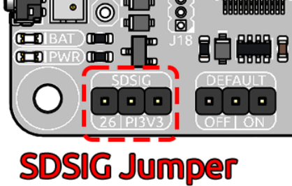
Provides shutdown detection for Raspberry Pi.
When bridged to PI3V3, it works with Raspberry Pi 4 and Pi 5.
When shorted to Pin 26, it supports Pi 3 and Pi Zero.
After proper configuration, PiPower5 will cut power automatically once the Raspberry Pi shuts down.
Default ON/OFF Jumper

This jumper is used to select whether the USB power output is enabled by default after a shutdown. Use the jumper cap to connect the pins labeled ON or OFF to make the selection.
If the jumper cap is positioned on the left and connected to OFF, inserting USB power after a shutdown will not activate the output.
If the jumper cap is positioned on the right and connected to ON, inserting USB power after a shutdown will activate the output.
This feature is typically used for devices that need to start automatically, such as personal servers. For example, if there is a power outage, PiPower 5 will take over the Raspberry Pi’s power supply, ensuring a safe shutdown. Once power is restored, PiPower 5 automatically powers on the Raspberry Pi, eliminating the need for manual intervention.
Pin Headers for RPi
The pin header is designed for direct connection to a Raspberry Pi, including both I2C communication and power supply.

The header supports stacking additional HATs. However, note that the I2C pins and pin 26 are already connected and may need to be managed carefully to avoid conflicts.
Raspberry Pi |
MCU On Board |
|---|---|
SDA |
SDA |
SCL |
SCL |
GPIO26 |
SHUTDOWN |
ID_SD |
ID_EEPROM SDA |
ID_SC |
ID_EEPROM SCL |
I2C Communication
I2C address: 0x5C
The onboard microcontroller collects various signals from the board and stores them in registers. These signals can be accessed via I2C using the following register tables.
| Name | Address | Data Length | Data Type | Unit | Description |
|---|---|---|---|---|---|
| Input Voltage | 0 | 2 | u16 | mV | - |
| Input Current | 2 | 2 | u16 | mA | - |
| Output Voltage | 4 | 2 | u16 | mV | - |
| Output Current | 6 | 2 | u16 | mA | - |
| Battery Voltage | 8 | 2 | u16 | mV | - |
| Battery Current | 10 | 2 | i16 | mA | - |
| Battery Percentage | 12 | 1 | u8 | % | - |
| Battery Capacity | 13 | 2 | u16 | mAh | - |
| Power Source | 15 | 1 | u8 | - | 0: Battery not supplying power. 1: Battery supplying power. |
| USB Connection Status | 16 | 1 | u8 | - | 0: USB unplugged. 1: USB plugged in. |
| RESERVED | 17 | 1 | - | - | - |
| Charging Status | 18 | 1 | u8 | - | 0: Not charging. 1: Charging. |
| Fan Power | 19 | 1 | u8 | - | Fan power level (0–100). |
| Shutdown Request | 20 | 1 | u8 | - | 1: Triggered by low battery. 2: Triggered by pressing the power button. |
| Firmware Version (Major) | 128 | 1 | u8 | - | - |
| Firmware Version (Minor) | 129 | 1 | u8 | - | - |
| Firmware Version (Patch) | 130 | 1 | u8 | - | - |
| Reset Code | 131 | 1 | u8 | - | MCU reset reason code. |
| RTC Year | 132 | 1 | u8 | - | - |
| RTC Month | 133 | 1 | u8 | - | - |
| RTC Day | 134 | 1 | u8 | - | - |
| RTC Hour | 135 | 1 | u8 | - | - |
| RTC Minute | 136 | 1 | u8 | - | - |
| RTC Second | 137 | 1 | u8 | - | - |
| RTC Sub-Second | 138 | 1 | u8 | 1/128 s | RTC sub-second (1/128 second). |
| Always-On Feature | 139 | 1 | u8 | - | 0: Enabled. 1: Disabled. |
| Board ID | 140 | 1 | u8 | - | Board identification: 0: Pironman U1. 1: Pironman 4. 2: PiPower 3. 4: PiPower 5. |
| RESERVED | 141 | 1 | - | - | - |
| RESERVED | 142 | 1 | - | - | - |
| Shutdown Percentage | 143 | 1 | u8 | - | Current low battery shutdown percentage threshold. |
| RESERVED | 144 | 1 | - | - | - |
| Name | Address | Data Length | Data Type | Unit | Description |
|---|---|---|---|---|---|
| Fan Power | 0 | 1 | u8 | - | Set fan speed (0–100). |
| RTC Year | 1 | 1 | u8 | - | Set RTC year. |
| RTC Month | 2 | 1 | u8 | - | Set RTC month. |
| RTC Day | 3 | 1 | u8 | - | Set RTC day. |
| RTC Hour | 4 | 1 | u8 | - | Set RTC hour. |
| RTC Minute | 5 | 1 | u8 | - | Set RTC minute. |
| RTC Second | 6 | 1 | u8 | - | Set RTC second. |
| RTC Sub-Second | 7 | 1 | u8 | 1/128 s | Set RTC sub-second. |
| RTC Setting | 8 | 1 | u8 | - | Enable RTC setting: 1: Enabled. |
| Shutdown Percentage | 9 | 1 | u8 | - | Set low battery shutdown percentage threshold (0–100). |
| Power Off Percentage | 10 | 1 | u8 | - | Set low battery power-off percentage threshold (0–100). |