L298N Module
This L298N Motor Driver Module is a high power motor driver module for driving DC and Stepper Motors. This module consists of an L298 motor driver IC and a 78M05 5V regulator. L298N Module can control up to 4 DC motors, or 2 DC motors with directional and speed control.
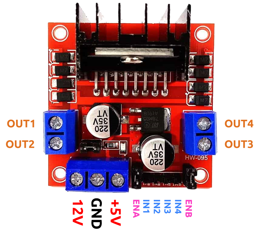
IN1 & IN2: Motor A input pins. Used to control the spinning direction of Motor A
IN3 & IN4: Motor B input pins. Used to control the spinning direction of Motor B
ENA: Enables PWM signal for Motor A. Here it has been connected to 5V with a jumper cap.
ENB: Enables PWM signal for Motor B. Here it has been connected to 5V with a jumper cap.
OUT1 & OUT2: Output pins of Motor A
OUT3 & OUT4: Output pins of Motor B
12V: 12V input from DC power Source
5V: Supplies power for the switching logic circuitry inside L298N IC
GND: Ground pin
Features
Driver Model: L298N 2A
Driver Chip: Double H Bridge L298N
Motor Supply Voltage (Maximum): 46V
Motor Supply Current (Maximum): 2A
Logic Voltage: 5V
Driver Voltage: 5-35V
Driver Current:2A
Logical Current:0-36mA
Maximum Power (W): 25W
Current Sense for each motor
Heatsink for better performance
Power-On LED indicator
Operating Principle
The driver module can drive two motors. The enabled terminals ENA and ENB are effective at high level.
The working relationship between ENA and IN1,IN2 is as follows:
ENA |
IN1 |
IN2 |
The state of Motor A |
|---|---|---|---|
0 |
X |
X |
Stop |
1 |
0 |
0 |
Brake |
1 |
0 |
1 |
Rotate clockwise |
1 |
1 |
0 |
Rotate counterclockwise |
1 |
1 |
1 |
Brake |
The working relationship between ENB and IN3,IN4 is as follows.
ENB |
IN3 |
IN4 |
The state of Motor B |
|---|---|---|---|
0 |
X |
X |
Stop |
1 |
0 |
0 |
Brake |
1 |
0 |
1 |
Rotate clockwise |
1 |
1 |
0 |
Rotate counterclockwise |
1 |
1 |
1 |
Brake |
About 5V Enable Cap
The L298N Motor Driver module consists of an L298 Motor Driver IC, 78M05 Voltage Regulator, resistors, capacitor, Power LED, 5V jumper in an integrated circuit.
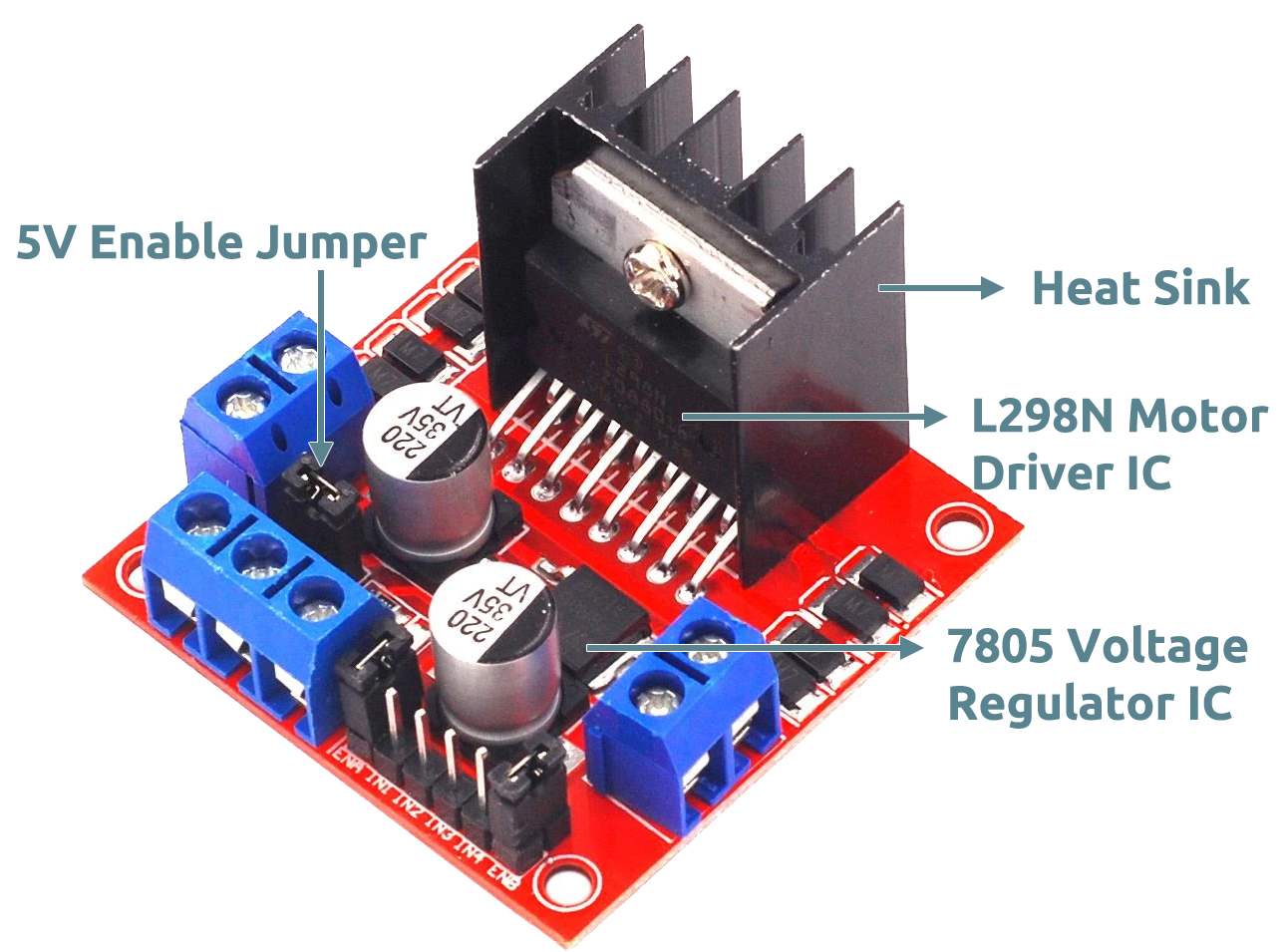
78M05 Voltage regulator will be enabled only when the jumper is placed. When the power supply is less than or equal to 12V, then the internal circuitry will be powered by the voltage regulator and the 5V pin can be used as an output pin to power the microcontroller.
The jumper should not be placed when the power supply is greater than 12V and separate 5V should be given through 5V terminal to power the internal circuitry.