Note
Hello, welcome to the SunFounder Raspberry Pi & Arduino & ESP32 Enthusiasts Community on Facebook! Dive deeper into Raspberry Pi, Arduino, and ESP32 with fellow enthusiasts.
Why Join?
Expert Support: Solve post-sale issues and technical challenges with help from our community and team.
Learn & Share: Exchange tips and tutorials to enhance your skills.
Exclusive Previews: Get early access to new product announcements and sneak peeks.
Special Discounts: Enjoy exclusive discounts on our newest products.
Festive Promotions and Giveaways: Take part in giveaways and holiday promotions.
👉 Ready to explore and create with us? Click [here] and join today!
Hardware Introduction
Pinout

- Power Port
6.0V-8.4V XH2.54 3pin power input.
Powering the Raspberry Pi and Robot HAT at the same time.
- Power Switch
Turn on/off the power of the robot HAT.
- Type-C Charge Port
Insert the Type-C cable to charge the battery.
At the same time, the charging indicator lights up in red color.
When the battery is fully charged, the charging indicator turns off.
If the USB cable is still plugged in about 4 hours after it is fully charged, the charging indicator will blink to prompt.
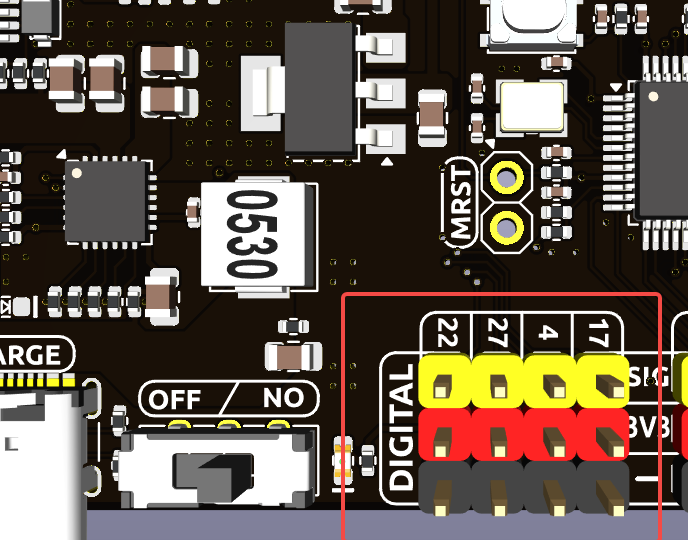
- Digital Pin
4-channel digital pins, D0-D3.
Pin: Digital IO.
API: class Pin.
- ADC Pin
- PWM Pin
- Motor Port
4-channel XH2.54 motor ports.
Pin: Motor Port.
API: module motor.
- I2C Pin and I2C Port
- SPI Pin
P2.54 7-pin SPI interface.
Pin: SPI.
- UART Pin
P2.54 4-pin interface.
Pin: UART.
- WS2812 Port
1-channel WS2812 port.
Pin: WS2812 Port.
- RST Button
- USR Button
- Battery Indicator
Two LEDs light up when the voltage is higher than 7.6V.
One LED lights up in the 7.15V to 7.6V range.
Below 7.15V, both LEDs turn off.
- Speaker and MIC
Speaker: This is a 2030 audio chamber speaker.
Speaker Port: The Robot HAT is equipped with onboard I2S audio output, along with a 2030 audio chamber speaker, providing a mono sound output.
MIC: The Robot HAT is equipped with a MEMS microphone, which can be used to collect ambient sound.
Pin: Speaker and MIC.
API: class Music
Pin Mapping
Robot Hat V5 |
Raspberry Pi |
Raspberry Pi |
Robot Hat V5 |
|---|---|---|---|
NC |
3V3 |
5V |
5V |
SDA |
SDA |
5V |
5V |
SCL |
SCL |
GND |
GND |
DIGITAL 4 |
GPIO4 |
TXD |
TXD |
GND |
GND |
RXD |
RXD |
DIGITAL 17 |
GPIO17 |
GPIO18 |
I2S BCLK |
DIGITAL 27 |
GPIO27 |
GND |
GND |
DIGITAL 22 |
GPIO22 |
GPIO23 |
CHG |
NC |
3V3 |
GPIO24 |
NC |
SPI MOSI / WS2812 DOUT |
MOSI |
GND |
GND |
SPI MISO |
MISO |
GPIO25 |
USR BUTTON |
SPI SCLK |
SCLK |
CE0 |
SPI CE0 |
GND |
GND |
CE1 |
NC |
NC |
ID_SD |
ID_SC |
NC |
MCU Reset |
GPIO5 |
GND |
GND |
(SPI)BSY |
GPIO6 |
GPIO12 |
Speaker Enable |
NC |
GPIO13 |
GND |
GND |
I2S LRCLK |
GPIO19 |
GPIO16 |
RST BUTTON |
USER LED |
GPIO26 |
GPIO20 |
I2S DATAIN |
GND |
GND |
GPIO21 |
I2S DATAOUT |
Digital IO
Robot HAT has 4 sets of P2.54 3Pin digital pins.
Robot Hat V5 |
Raspberry Pi |
|---|---|
17 |
GPIO17 |
4 |
GPIO4 |
27 |
GPIO27 |
22 |
GPIO22 |
ADC
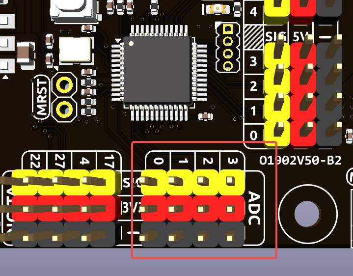
The Robot HAT features four sets of 3 Pin ADC (Analog to Digital Converter) pins, each spaced 2.54mm apart. These pins operate at a 3.3V power supply. The ADC function, offering 12-bit precision, is facilitated by an onboard microcontroller. Detailed instructions for reading ADC values are provided in the On-Board MCU section.
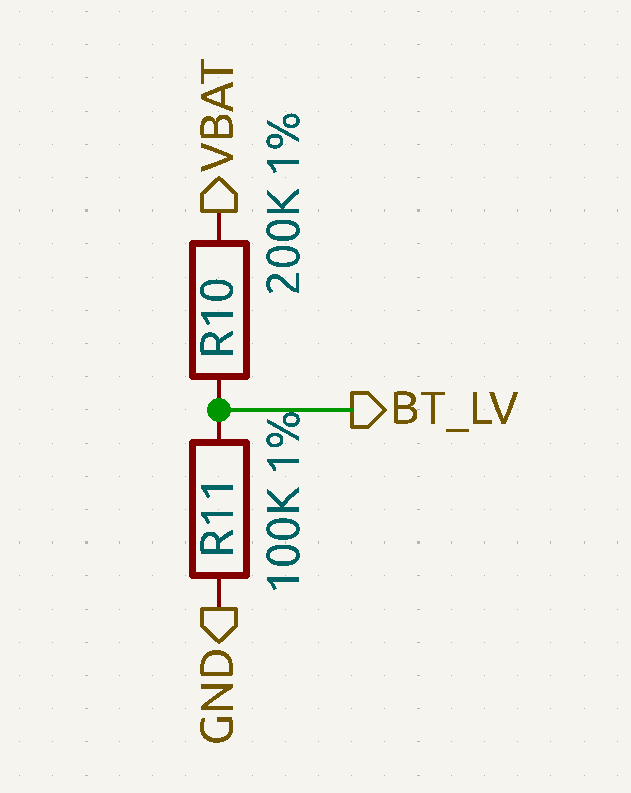
Also, ADC channel A4 is connected to the battery through a voltage divider using resistors, which will be used to measure the battery voltage to estimate the approximate battery charge.
The voltage divider ratio is 200K/100K, so:
A4 voltage (Va4) = value_A4 / 4095.0 * 3.3
Battery voltage (Vbat) = Va4*3
Battery voltage (Vbat) = value_A4 / 4095.0 * 3.3 * 3
PWM
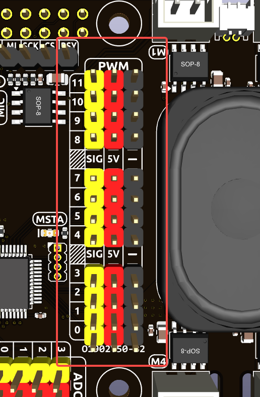
Robot HAT has 4 sets of 3 Pin PWM pins, each spaced 2.54mm apart, and the power supply is 5V. The method of using the PWM is described in detail in On-Board MCU.
Note
PWM13 ~ 19 channels are used for motor drive.
I2C

The Robot HAT has two I2C interfaces. One is the P2.54 4-pin interface, and the other is the SH1.0 4-pin interface, which is compatible with QWIIC and STEMMA QT. These I2C interfaces are connected to the Raspberry Pi’s I2C interface via GPIO2 (SDA) and GPIO3 (SCL). The board also features an On-Board MCU, and the two signal lines have 10K pull-up resistors.
SPI
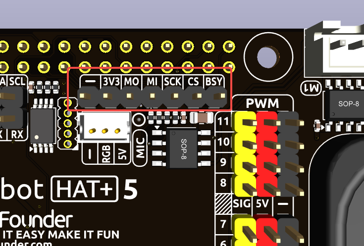
The SPI interface of the Robot HAT is a 7-pin P2.54 interface. It connects to the SPI interface of the Raspberry Pi and includes an additional I/O pin that can be used for purposes such as interrupts or resets.
Robot Hat V5 |
Raspberry Pi |
|---|---|
BSY |
GPIO6 |
CS |
CE0(GPIO8) |
SCK |
SCLK(GPIO11) |
MI |
MISO(GPIO9) |
MO |
MOSI(GPIO10) |
3V3 |
3.3V Power |
GND |
Ground |
UART
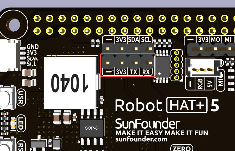
The UART interface of the Robot HAT is a 4-pin P2.54 interface. It connects to the Raspberry Pi’s GPIO14 (TXD) and GPIO15 (RXD) pins.
WS2812 Port

The Robot HAT comes with 1 WS2812 port (ZH1.5 3 Pin), which can be used to control 1 WS2812 LED strip.
This Pin is shared with SPI MOSI, so it can not be used as SPI MOSI at the same time.
Buttons
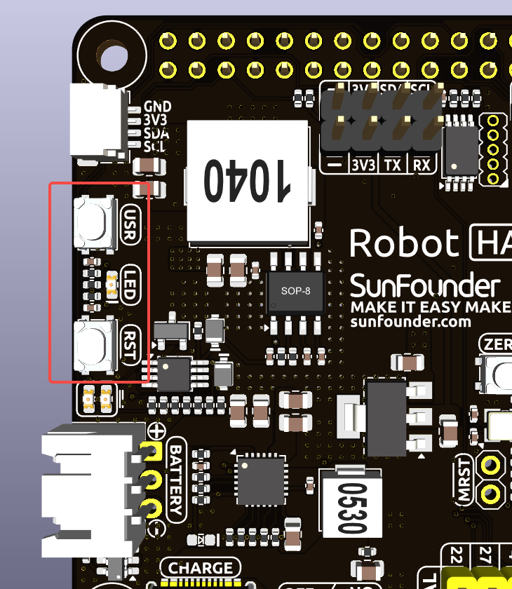
The Robot HAT comes with 1 LED and 2 buttons, all directly connected to the Raspberry Pi’s GPIO pins. The RST button, when using Ezblock, serves as a button to restart the Ezblock program. If not using Ezblock, the RST button does not have a predefined function and can be fully customized according to your needs.
Robot Hat V4 |
Raspberry Pi |
|---|---|
LED |
GPIO26 |
USR |
GPIO25 |
RST |
GPIO16 |
Speaker and MIC
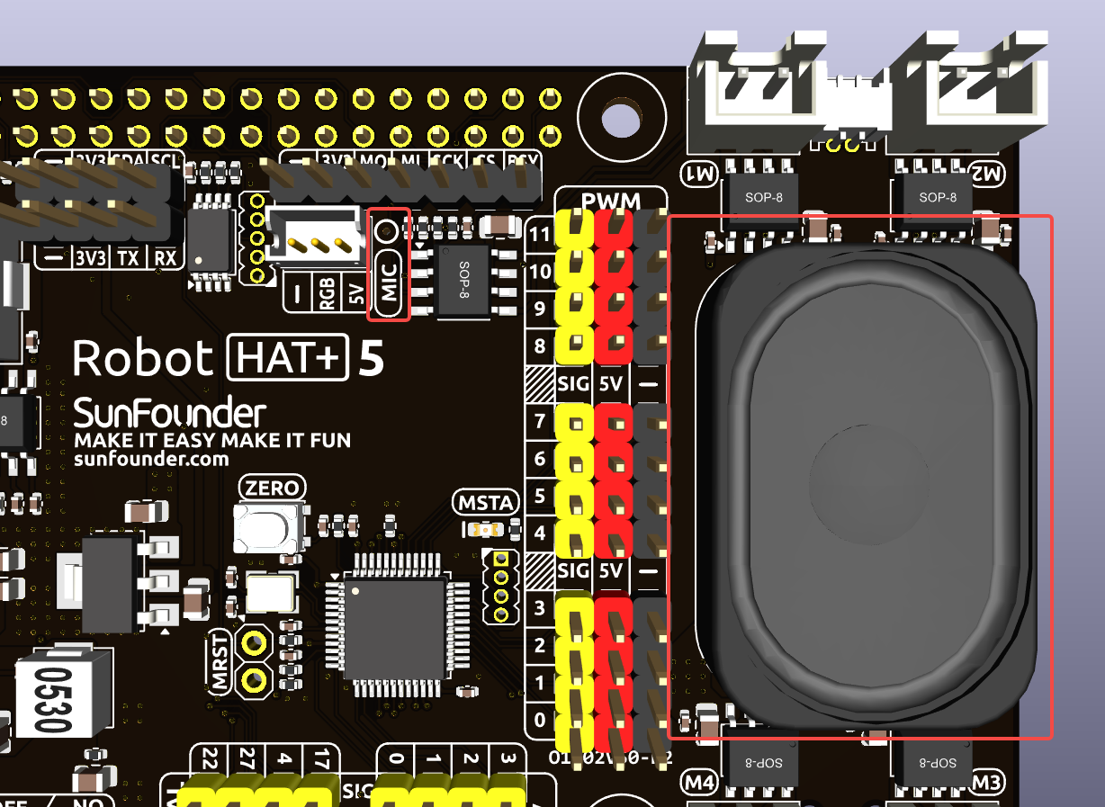
The Robot HAT is equipped with onboard I2S audio output/input, along with a 2030 audio chamber speaker, providing a mono sound output. The onboard microphone can be used to receive audio signals.
I2S |
Raspberry Pi |
|---|---|
WS |
GPIO19 |
SCLK |
GPIO18 |
Audio OUT (Speaker) |
GPIO21 |
Aduio IN (MIC) |
GPIO20 |
The speaker has a switch to control the speaker’s on/off status, which is connected to the Raspberry Pi’s GPIO 12. When the switch is turned on, the speaker will be enabled, and when the switch is turned off, the speaker will be disabled. If you do not need the speaker, you can turn off the switch to protect it.
I2S |
Raspberry Pi |
|---|---|
Switch |
GPIO12 |
Enable |
High |
Disable |
Low |
Motor Port
The motor driver of the Robot HAT supports 4 channels and can be controlled using 8 PWM signals for direction and speed control.
Motor |
PWM |
|---|---|
Motor1 A |
PWM12 |
Motor1 B |
PWM13 |
Motor2 A |
PWM14 |
Motor2 B |
PWM15 |
Motor3 A |
PWM16 |
Motor3 B |
PWM17 |
Motor4 A |
PWM18 |
Motor4 B |
PWM19 |
The motor drive mode is as follow.
Battery Level Indicator
The battery level indicator on the Robot HAT monitors the battery voltage using a voltage divider method and serves as a reference for estimating the battery level. The relationship between the LED and voltage is as follows:
LED Battery |
Total Voltage |
|---|---|
2 LEDs on |
Greater than 7.3V |
1 LED on |
Greater than 6.9V |
Both LEDs off |
Less than 6.9V |
When any one of the batteries reaches or exceeds 4.1V while the others are below that threshold, the charging current of that specific battery will be reduced.
Servo Zeroing Button
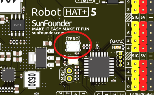
The servo zeroing button is used to calibrate the servo’s zero position. When you press the button twice, all the PWM signals will be set to 1500us pulse, 20000us period. That is, the servo will be in the middle position. You should secure the servo arm to the servo in this state.
Press the button twice again, all the PWM signals will be set to 0 pulse.