Note
Hello, welcome to the SunFounder Raspberry Pi & Arduino & ESP32 Enthusiasts Community on Facebook! Dive deeper into Raspberry Pi, Arduino, and ESP32 with fellow enthusiasts.
Why Join?
Expert Support: Solve post-sale issues and technical challenges with help from our community and team.
Learn & Share: Exchange tips and tutorials to enhance your skills.
Exclusive Previews: Get early access to new product announcements and sneak peeks.
Special Discounts: Enjoy exclusive discounts on our newest products.
Festive Promotions and Giveaways: Take part in giveaways and holiday promotions.
👉 Ready to explore and create with us? Click [here] and join today!
1.1.6 LED Dot Matrix Module
Introduction
In this project, you will learn about LED Matrix Module. LED Matrix Module uses the MAX7219 driver to drive the 8 x 8 LED Matrix.
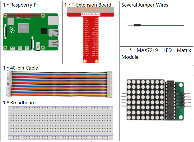
Required Components
In this project, we need the following components.
It’s definitely convenient to buy a whole kit, here’s the link:
Name |
ITEMS IN THIS KIT |
LINK |
|---|---|---|
Raphael Kit |
337 |
You can also buy them separately from the links below.
COMPONENT INTRODUCTION |
PURCHASE LINK |
|---|---|
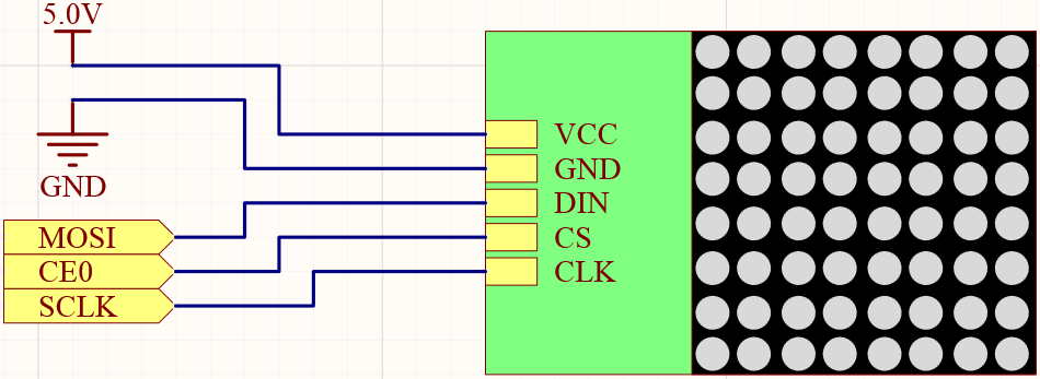
Schematic Diagram
T-Board Name |
physical |
wiringPi |
BCM |
SPIMOSI |
Pin 19 |
12 |
MOSI |
SPICE0 |
pin 24 |
10 |
CE0 |
SPISCLK |
Pin 23 |
14 |
SCLK |
Experimental Procedures
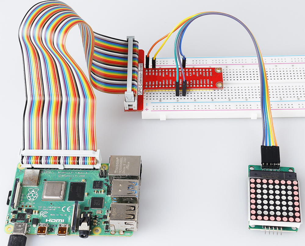
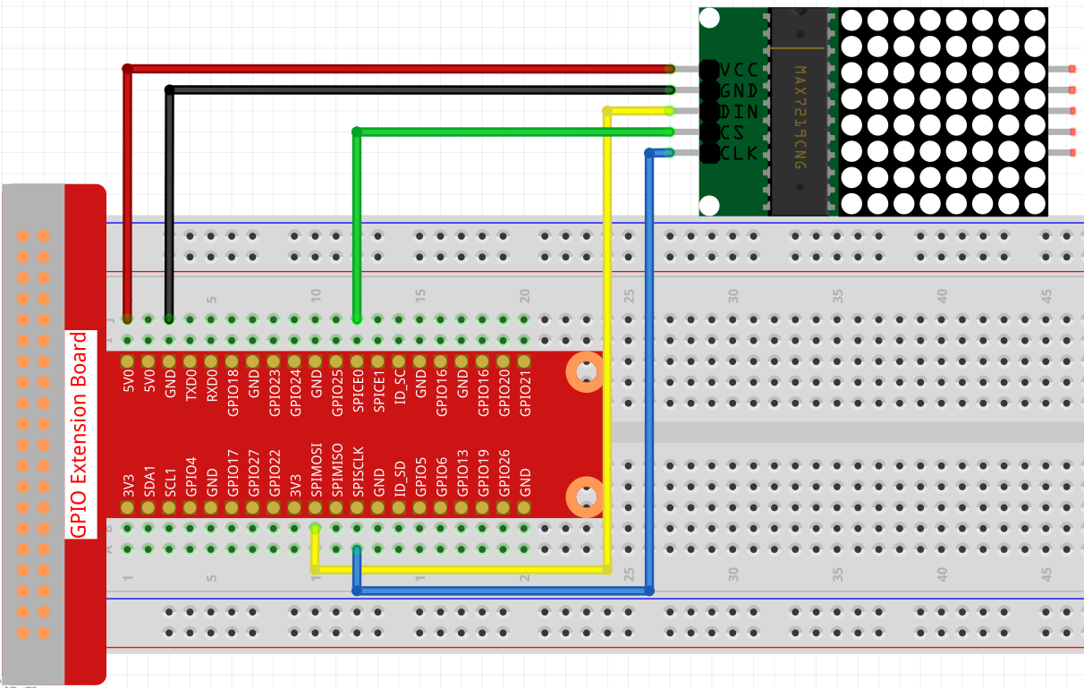
Step 1: Build the circuit.
Step 2: Turn on the SPI before starting the experiment, refer to SPI Configuration for details.
Step 3: Go to the folder of the code.
cd ~/raphael-kit/c/1.1.6/
Step 4: Compile the code.
make
Step 5:: Run the executable file.
sudo ./1.1.6_LedMatrix
After running the code, the LED Dot Matrix displays from square, heart and number 0 to 9 in sequence.
Note
If it does not work after running, or there is an error prompt: "wiringPi.h: No such file or directory", please refer to Install and Check the WiringPi.
Code
#include <wiringPi.h>
#include <wiringPiSPI.h>
#include <stdio.h>

#define SPI_CHANNEL    0           // Define SPI channel (0 or 1)
#define SPI_SPEED      1000000     // SPI speed set to 1 MHz

// Function to write data to a MAX7219 register
void max7219_write(unsigned char address, unsigned char data) {
    unsigned char buffer[2];
    buffer[0] = address;   // Register address to write to
    buffer[1] = data;      // Data to write into the register
    wiringPiSPIDataRW(SPI_CHANNEL, buffer, 2);  // Send data via SPI
}

// Function to initialize the MAX7219 display module
void max7219_init() {
    max7219_write(0x09, 0x00); // Decode Mode: No decoding for digits (useful for 7-segment displays)
    max7219_write(0x0A, 0x03); // Intensity: Set brightness level (0x00 to 0x0F)
    max7219_write(0x0B, 0x07); // Scan Limit: Display digits 0-7 (all 8 digits)
    max7219_write(0x0C, 0x01); // Shutdown Register: Normal operation (not in shutdown mode)
    max7219_write(0x0F, 0x00); // Display Test: Normal operation (no test mode)

    // Clear all digits on the display
    for (int i = 1; i <= 8; i++) {
        max7219_write(i, 0x00); // Write 0 to each digit register
    }
}

// Function to display a pattern on the MAX7219
void max7219_display(unsigned char *data) {
    for (int i = 1; i <= 8; i++) {
        max7219_write(i, data[i - 1]); // Write each row of the pattern to the display
    }
}

// Function to display a pattern for a specified duration
void display_pattern(const unsigned char pattern[8], int delay_ms) {
    max7219_display((unsigned char *)pattern); // Display the pattern
    delay(delay_ms);                           // Wait for the specified time in milliseconds
}

// Array of patterns to display
const unsigned char patterns[][8] = {
    // Square pattern
    {
        0b11111111, // Row 1
        0b10000001, // Row 2
        0b10000001, // Row 3
        0b10000001, // Row 4
        0b10000001, // Row 5
        0b10000001, // Row 6
        0b10000001, // Row 7
        0b11111111  // Row 8
    },
    // Heart pattern
    {
        0b01100110, // Row 1
        0b11111111, // Row 2
        0b11111111, // Row 3
        0b11111111, // Row 4
        0b01111110, // Row 5
        0b00111100, // Row 6
        0b00011000, // Row 7
        0b00000000  // Row 8
    },
    // Number 0
    {
        0b00111100, // Row 1
        0b01100110, // Row 2
        0b11000011, // Row 3
        0b11000011, // Row 4
        0b11000011, // Row 5
        0b11000011, // Row 6
        0b01100110, // Row 7
        0b00111100  // Row 8
    },
    // Number 1
    {
        0b00011000, // Row 1
        0b00111000, // Row 2
        0b01111000, // Row 3
        0b00011000, // Row 4
        0b00011000, // Row 5
        0b00011000, // Row 6
        0b01111110, // Row 7
        0b01111110  // Row 8
    },
    // Number 2
    {
        0b01111110, // Row 1
        0b11000011, // Row 2
        0b00000011, // Row 3
        0b00001110, // Row 4
        0b00110000, // Row 5
        0b11000000, // Row 6
        0b11111111, // Row 7
        0b00000000  // Row 8
    },
    // Number 3
    {
        0b01111110, // Row 1
        0b11000011, // Row 2
        0b00000011, // Row 3
        0b00111110, // Row 4
        0b00000011, // Row 5
        0b11000011, // Row 6
        0b01111110, // Row 7
        0b00000000  // Row 8
    },
    // Number 4
    {
        0b00001110, // Row 1
        0b00011110, // Row 2
        0b00110110, // Row 3
        0b01100110, // Row 4
        0b11111111, // Row 5
        0b00000110, // Row 6
        0b00000110, // Row 7
        0b00000000  // Row 8
    },
    // Number 5
    {
        0b11111111, // Row 1
        0b11000000, // Row 2
        0b11111110, // Row 3
        0b00000011, // Row 4
        0b00000011, // Row 5
        0b11000011, // Row 6
        0b01111110, // Row 7
        0b00000000  // Row 8
    },
    // Number 6
    {
        0b00111110, // Row 1
        0b01100000, // Row 2
        0b11000000, // Row 3
        0b11111110, // Row 4
        0b11000011, // Row 5
        0b11000011, // Row 6
        0b01111110, // Row 7
        0b00000000  // Row 8
    },
    // Number 7
    {
        0b11111111, // Row 1
        0b11000011, // Row 2
        0b00000110, // Row 3
        0b00001100, // Row 4
        0b00011000, // Row 5
        0b00110000, // Row 6
        0b00110000, // Row 7
        0b00000000  // Row 8
    },
    // Number 8
    {
        0b01111110, // Row 1
        0b11000011, // Row 2
        0b11000011, // Row 3
        0b01111110, // Row 4
        0b11000011, // Row 5
        0b11000011, // Row 6
        0b01111110, // Row 7
        0b00000000  // Row 8
    },
    // Number 9
    {
        0b01111110, // Row 1
        0b11000011, // Row 2
        0b11000011, // Row 3
        0b01111111, // Row 4
        0b00000011, // Row 5
        0b00000110, // Row 6
        0b01111100, // Row 7
        0b00000000  // Row 8
    },
};

int main() {
    if (wiringPiSetup() == -1) {
        printf("Failed to initialize WiringPi\n");
        return 1;
    }

    if (wiringPiSPISetup(SPI_CHANNEL, SPI_SPEED) == -1) {
        printf("Failed to initialize SPI\n");
        return 1;
    }

    max7219_init();  // Initialize the MAX7219 module

    // Display patterns in a loop
    while (1) {
        // Display the square pattern
        display_pattern(patterns[0], 1000);  // Display for 1000 milliseconds

        // Display the heart pattern
        display_pattern(patterns[1], 1000);

        // Display numbers 0-9
        for (int i = 2; i <= 11; i++) {
            display_pattern(patterns[i], 1000);
        }
    }

    return 0;
}
Code Analysis
Header Files:
wiringPi.h: Provides functions for GPIO control.wiringPiSPI.h: Provides functions for SPI communication.stdio.h: Standard input/output library for functions like printf.
Definitions:
SPI_CHANNEL: Specifies the SPI channel (0 or 1) used for communication.SPI_SPEED: Sets the SPI communication speed to 1 MHz.
#define SPI_CHANNEL    0           // Define SPI channel (0 or 1)
#define SPI_SPEED      1000000     // SPI speed set to 1 MHz
Function
max7219_write: Sends data to a specific register of the MAX7219 display driver.address: The address of the register to write to.data: The data to write into the register.Creates a buffer containing the address and data.
Uses
wiringPiSPIDataRWto send the buffer over SPI.
void max7219_write(unsigned char address, unsigned char data) {
    unsigned char buffer[2];
    buffer[0] = address;   // Register address to write to
    buffer[1] = data;      // Data to write into the register
    wiringPiSPIDataRW(SPI_CHANNEL, buffer, 2);  // Send data via SPI
}
Function
max7219_init: Initializes the MAX7219 display module with required settings.Sets decode mode to “no decode” since we are directly controlling the LEDs.
Sets intensity (brightness) to a moderate level (0x03).
Sets scan limit to 7 to enable all 8 digits (rows) of the display.
Exits shutdown mode to turn on the display.
Disables display test mode.
Clears the display by writing 0x00 to all digit registers.
void max7219_init() {
    max7219_write(0x09, 0x00); // Decode Mode: No decoding for digits (useful for 7-segment displays)
    max7219_write(0x0A, 0x03); // Intensity: Set brightness level (0x00 to 0x0F)
    max7219_write(0x0B, 0x07); // Scan Limit: Display digits 0-7 (all 8 digits)
    max7219_write(0x0C, 0x01); // Shutdown Register: Normal operation (not in shutdown mode)
    max7219_write(0x0F, 0x00); // Display Test: Normal operation (no test mode)

    // Clear all digits on the display
    for (int i = 1; i <= 8; i++) {
        max7219_write(i, 0x00); // Write 0 to each digit register
    }
}
Function
max7219_display: Updates the display with a given 8-byte pattern.data: An array containing the pattern to display.Iterates through each of the 8 rows (digits) and writes the corresponding data.
void max7219_display(unsigned char *data) {
    for (int i = 1; i <= 8; i++) {
        max7219_write(i, data[i - 1]); // Write each row of the pattern to the display
    }
}
Function
display_pattern: Displays a pattern for a specified amount of time.pattern: The pattern to display (array of 8 bytes).delay_ms: Duration to display the pattern in milliseconds.Calls
max7219_displayto show the pattern.Uses
delayto wait for the specified duration.
void display_pattern(const unsigned char pattern[8], int delay_ms) {
    max7219_display((unsigned char *)pattern); // Display the pattern
    delay(delay_ms);                           // Wait for the specified time in milliseconds
}
Array patterns:
Contains predefined patterns for the square, heart, and numbers 0-9.
Each pattern is an array of 8 bytes, representing 8 rows of the 8x8 LED matrix.
Each byte uses binary notation where each bit represents an LED (1 for on, 0 for off).
const unsigned char patterns[][8] = {
    // Square pattern
    {
        0b11111111, // Row 1
        0b10000001, // Row 2
        0b10000001, // Row 3
        0b10000001, // Row 4
        0b10000001, // Row 5
        0b10000001, // Row 6
        0b10000001, // Row 7
        0b11111111  // Row 8
    },
    ...
    // Number 9
    {
        ...
    },
};
Function main:
Initializes
WiringPiandSPIinterface.if (wiringPiSetup() == -1) { printf("Failed to initialize WiringPi\n"); return 1; } if (wiringPiSPISetup(SPI_CHANNEL, SPI_SPEED) == -1) { printf("Failed to initialize SPI\n"); return 1; }
Calls
max7219_initto configure the MAX7219 module.max7219_init(); // Initialize the MAX7219 module
Enters an infinite loop to display the patterns continuously. Displays each pattern for 1 second before moving to the next.
while (1) {
    // Display the square pattern
    display_pattern(patterns[0], 1000);  // Display for 1000 milliseconds

    // Display the heart pattern
    display_pattern(patterns[1], 1000);

    // Display numbers 0-9
    for (int i = 2; i <= 11; i++) {
        display_pattern(patterns[i], 1000);
    }
}
Understanding the Patterns
Binary Representation:
Each pattern is defined using binary literals (0b prefix).
Each byte corresponds to a row on the 8x8 LED matrix.
Each bit within the byte represents a column (LED) in that row.
The most significant bit (leftmost) corresponds to the first LED on the left.
Creating Custom Patterns:
You can create new patterns by defining new arrays of 8 bytes.
Each pattern can be added to the patterns array.
Update the display loop in main to include your new patterns.
Adjustments and Customization
Changing Brightness: Modify the intensity level in
max7219_init:max7219_write(0x0A, brightness_level); // brightness_level between 0x00 and 0x0F
Modifying Display Time: Change the
delay_msparameter indisplay_patterncalls to adjust how long each pattern is displayed.
Phenomenon Picture