Note
Hello, welcome to the SunFounder Raspberry Pi & Arduino & ESP32 Enthusiasts Community on Facebook! Dive deeper into Raspberry Pi, Arduino, and ESP32 with fellow enthusiasts.
Why Join?
Expert Support: Solve post-sale issues and technical challenges with help from our community and team.
Learn & Share: Exchange tips and tutorials to enhance your skills.
Exclusive Previews: Get early access to new product announcements and sneak peeks.
Special Discounts: Enjoy exclusive discounts on our newest products.
Festive Promotions and Giveaways: Take part in giveaways and holiday promotions.
👉 Ready to explore and create with us? Click [here] and join today!
Features
Pass Through Charging
Shutdown Current:< 0.5mA
- Input:
USB Type-C, 5V/3A
Battery Input
- Output:
USB Type-A, 5V/3A
2x4P P2.54 pin headers
Charging Power:7.4V/1A 7.4W
- Equipped Battery
Type: 3.7V Lithium-ion batteries x 2
Capacity: 2000mAh
Connector: PH2.0, 5P
Over Discharge Protection Voltage:3.2V
Overcharge Protection Voltage:4.2V
Dimension: 90mm x 60mm x 24.9mm
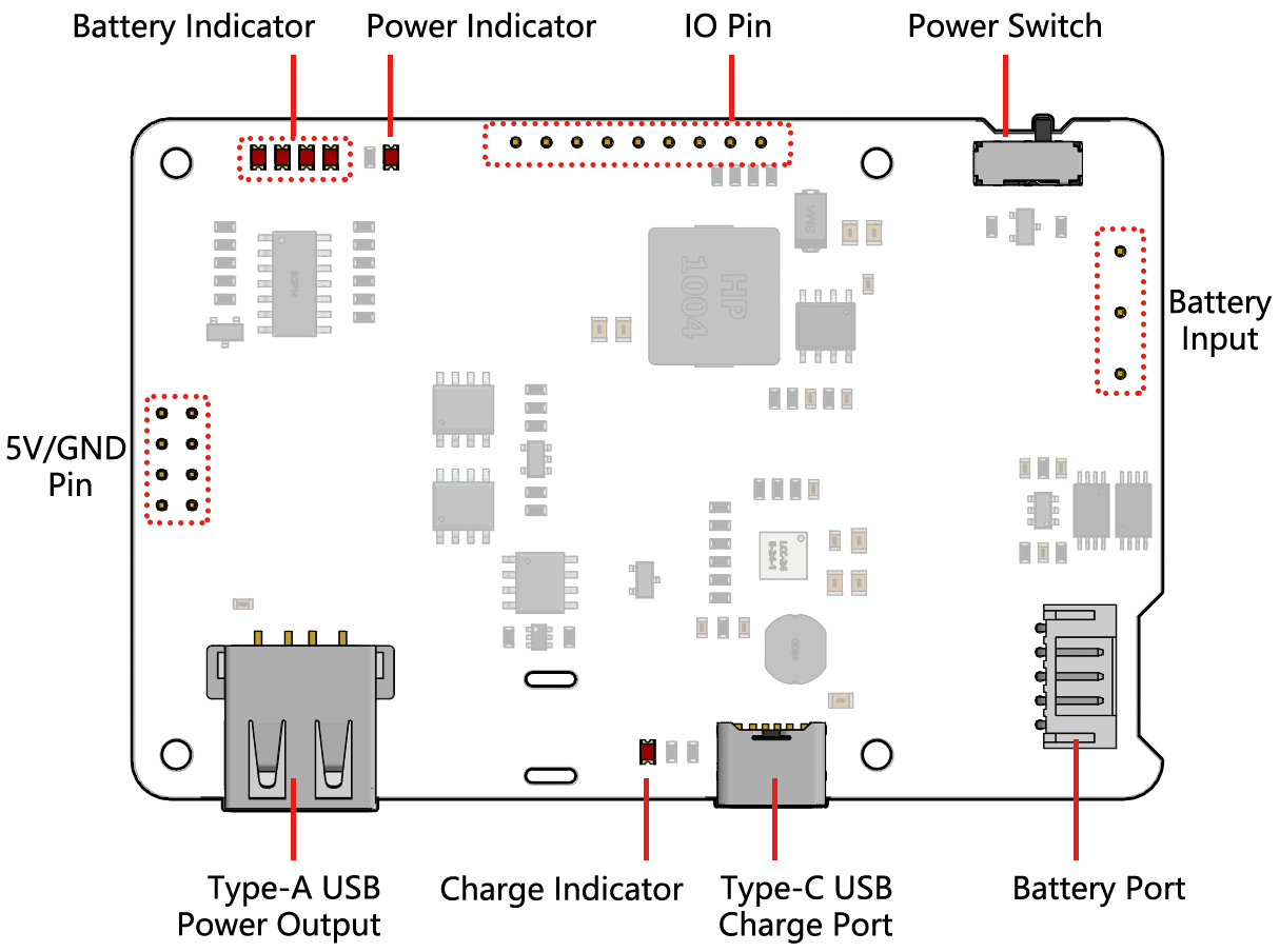
- On-board Indicators
1 x Charging Indicator (CHG)
1 x Power Indicator (PWR)
4 Battery Indicators (D4 ~ D7)
About Charge and Discharge
Switch Power Path
PiPower V2 has the function of integrated power, which can automatically switch the power path to reduce battery consumption.
If an external power supply is connected, the 5V output is directly output from the external power supply, and the power switch can be used to turn it on or off. Additionally, the external power supply can charge the battery at low current.
When the external power supply is unplugged, PiPower switches to battery step-down power supply, seamless switching to protect the device.
Charging Power
Charging current will be switched according to the state of the power switch.
PiPower does not provide power to external devices when the power switch is off. This time, the charging power is 7W, and it takes about 2 hours to charge from 0% to 100%.
External power supply will power the connected device directly when the power switch is on. Charging power is reduced to less than 1W to ensure power supply current.
Over-discharge Protection
When the single battery voltage is below 3.2V, the battery protection activates and the battery is no longer discharged.
When the battery is unplugged, due to the mechanism of the on-board over-discharge protection circuit, the voltage will be considered too low, thus activating the protection circuit; when you replug the battery into the PiPower, the battery will not work properly, at this time, you need to plug the Type C cable into the charging port to turn off the protection circuit, and the battery can be used normally.
Overcharge Protection
Charging ends when the total battery voltage reaches 8.4V.
Charge Balance
When a single battery exceeds 4.2V, the voltage divider resistor channel conducts and the battery charging current is reduced or even discharged.
Temperature
When the output power reaches the maximum nominal 5V/3A, the temperature of DC-DC buck chip U1 will rise to about 70-80 degrees Celsius, so be careful not to touch it to prevent burns and keep ventilation. When the temperature reaches the DC-DC protection temperature of 75 degrees Celsius, the DC-DC will shut down to prevent overheating damage.
Battery Indicators
The relationship between the battery indicators and voltage is as follows:
4 LEDs all on: voltage > 7.8V
3 LEDs on: voltage > 7.36V
2 LEDs on: voltage >6.96V
1 LED on: voltage > 6.6V
4 LEDs all off: voltage <6.6V,at this time,batteries need to be charged.
External Battery
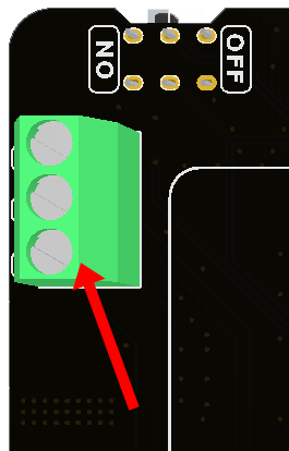
You can connect your own battery using the Screw Terminal.
Warning
Do not connect the external battery and the included battery at the same time!
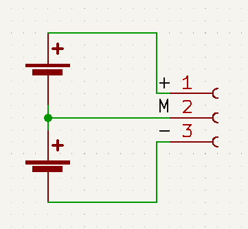
The external battery only supports two 3.7V lithium batteries connected in series. The interface has three pins: “+”, “M”, and “-”. They should be connected to the battery’s positive terminal, the middle of the two batteries, and the battery’s negative terminal, respectively.
The PiPower board has an onboard battery protection circuit, offering over-discharge, overcharge, and overcurrent protection. Therefore, it’s recommended not to use batteries with their own protection boards.
The ‘M’ interface primarily serves the board’s protection circuit for single-cell battery protection and balanced charging currents during charging. If you don’t require protection and balanced charging features, you can omit connecting to the ‘M’ interface.
About IO Pins
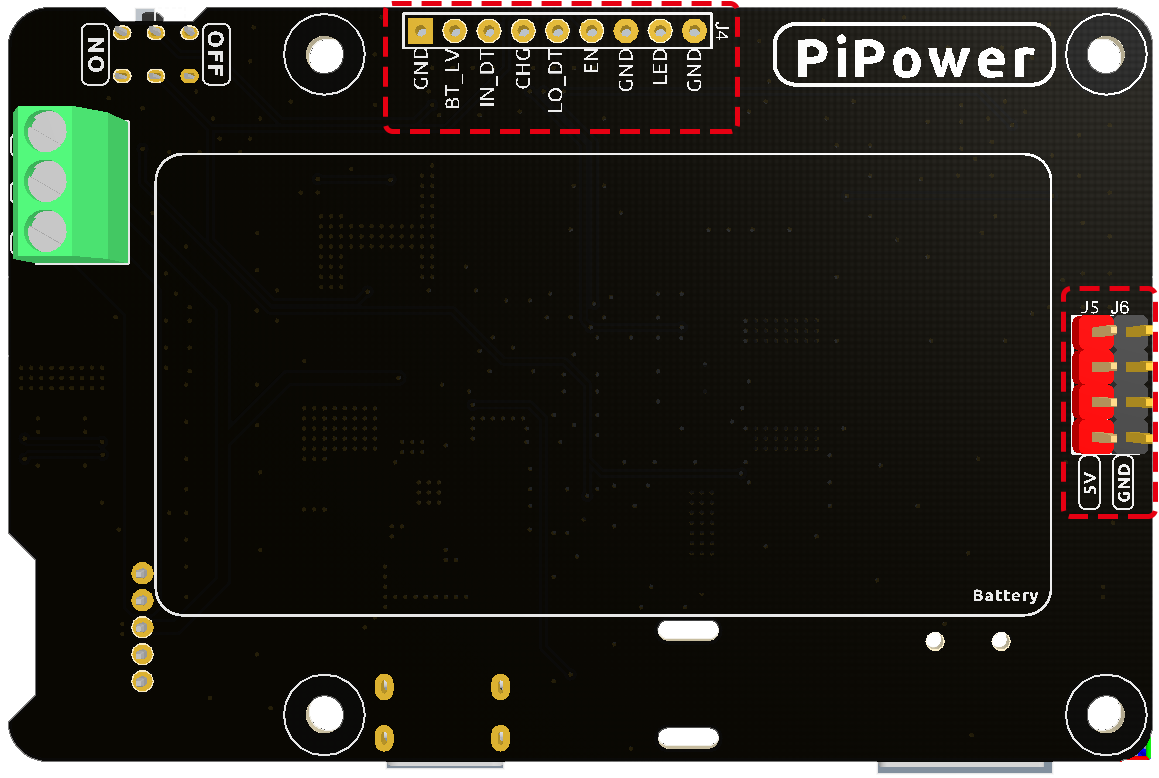
In order to meet the DIY needs of customers, multiple signal pins are provided on the PiPower, but they are not soldered by default.
GND: Ground input
BT_LV: Get the battery voltage pin. The voltage of this pin is equal to 1/3 of the battery voltage.
IN_DT: Input detect pin. Used to determine if there is USB power input, if so, this pin outputs high.
CHG: Charging status indication pin. This pin is high when charging.
LO_DT: Battery low voltage status pin. In normal state, this pin is low. When low battery voltage is detected, this pin is high.
EN: Switch signal pin. the EN pin can be connected to an external switch, put the pin to ground, the PiPower is off. The external switch can not use self-recovery button or key, etc. The EN pin is only effective when the on-board switch is turned on.
GND: Ground input
LED: Power indicator pin. Output 5V at power on, need to add current limiting resistor in the middle when connect an external LED.
GND: Ground input
About Battery
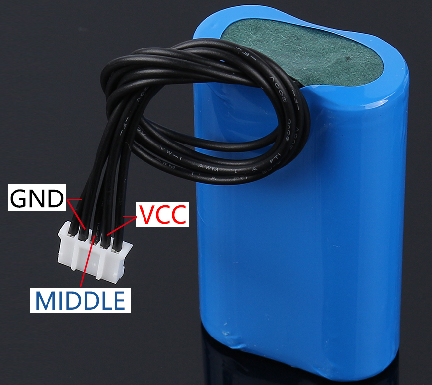
VCC: Battery positive terminal, here there are two sets of VCC and GND is to increase the current and reduce the resistance.
Middle: To balance the voltage between the two cells and thus protect the battery.
GND: Negative battery terminal.
This is a custom battery pack made by SunFounder consisting of two 3.7V 18650 batteries with a capacity of 2200mAh. The connector is PH2.0-5P, which can be charged directly after being inserted into the PiPower.