4.1 Turn the Knob
Potentiometer is a resistor component with 3 terminals and its resistance value can be adjusted according to some regular variation.
Required Components
In this project, we need the following components.
It’s definitely convenient to buy a whole kit, here’s the link:
Name |
ITEMS IN THIS KIT |
LINK |
|---|---|---|
3 in 1 Starter Kit |
380+ |
You can also buy them separately from the links below.
COMPONENT INTRODUCTION |
PURCHASE LINK |
|---|---|
Schematic
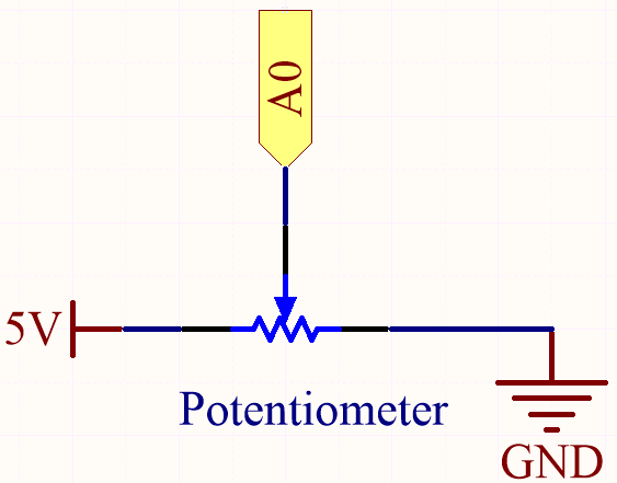
In this example, we use the analog pin (A0) to read the value of the potentiometer. By rotating the axis of the potentiometer, you can change the distribution of resistance among these three pins, changing the voltage on the middle pin. When the resistance between the middle and a outside pin connected to 5V is close to zero (and the resistance between the middle and the other outside pin is close to 10kΩ), the voltage at the middle pin is close to 5V. The reverse operation (the resistance between the middle and a outside pin connected to 5V is close to 10kΩ) will make the voltage at the middle pin be close to 0V.
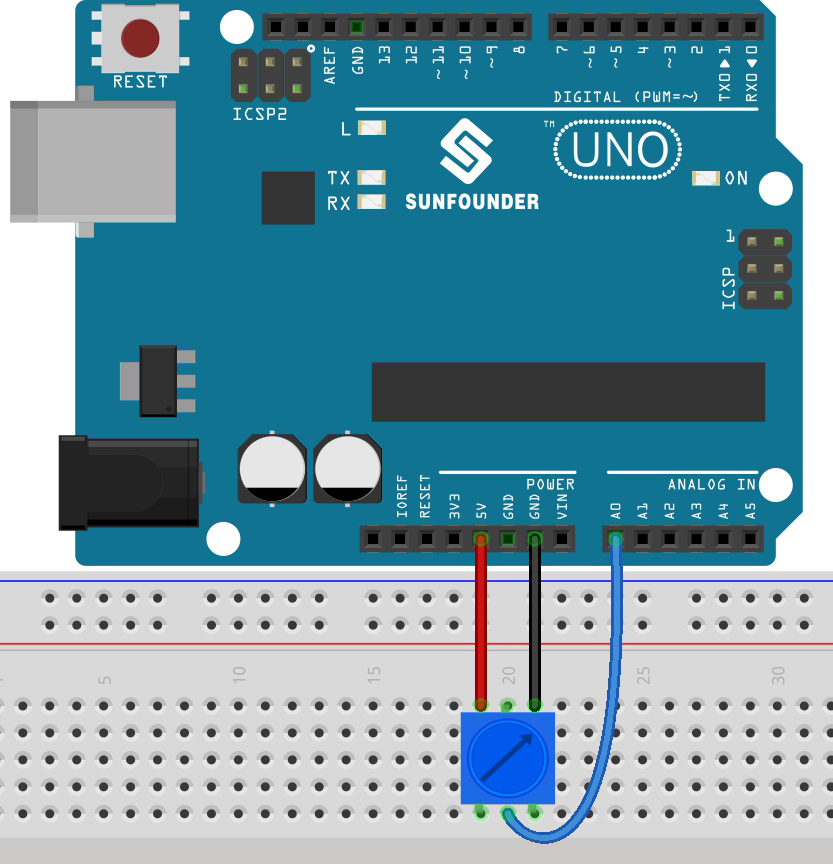
Wiring
Code
Note
You can open the file
4.1.turn_the_knob.inounder the path of3in1-kit\basic_project\4.1.turn_the_knob.Or copy this code into Arduino IDE.
Or upload the code through the Arduino Web Editor.
After uploading the codes to the board, you can open the serial monitor to see the reading value of the pin. When rotating the axis of the potentiometer, the serial monitor will print the value 「0」~「1023」.