4.3 Toggle the Joystick
The joystick should be very familiar to anyone who plays video games regularly. It is usually used to move characters or rotate the screen.
Our movements can be read by the Joystick, which works on a very simple principle. It consists of two potentiometers that are perpendicular to each other. These two potentiometers measure the analog value of the joystick in both vertical and horizontal directions, producing a value (x,y) in a planar right-angle coordinate system.
This kit also includes a joystick with a digital input. It is activated when the joystick is pressed.
Required Components
In this project, we need the following components.
It’s definitely convenient to buy a whole kit, here’s the link:
Name |
ITEMS IN THIS KIT |
LINK |
|---|---|---|
3 in 1 Starter Kit |
380+ |
You can also buy them separately from the links below.
COMPONENT INTRODUCTION |
PURCHASE LINK |
|---|---|
- |
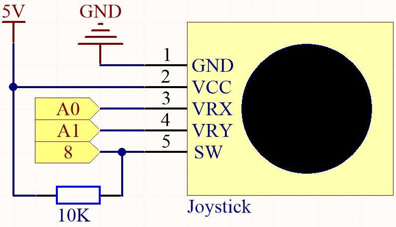
Schematic
Note
The SW pin is connected to a 10K pull-up resistor, the reason is to be able to get a stable high level on the SW pin (Z axis) when the joystick is not pressed; otherwise the SW is in a suspended state and the output value may vary between 0/1.
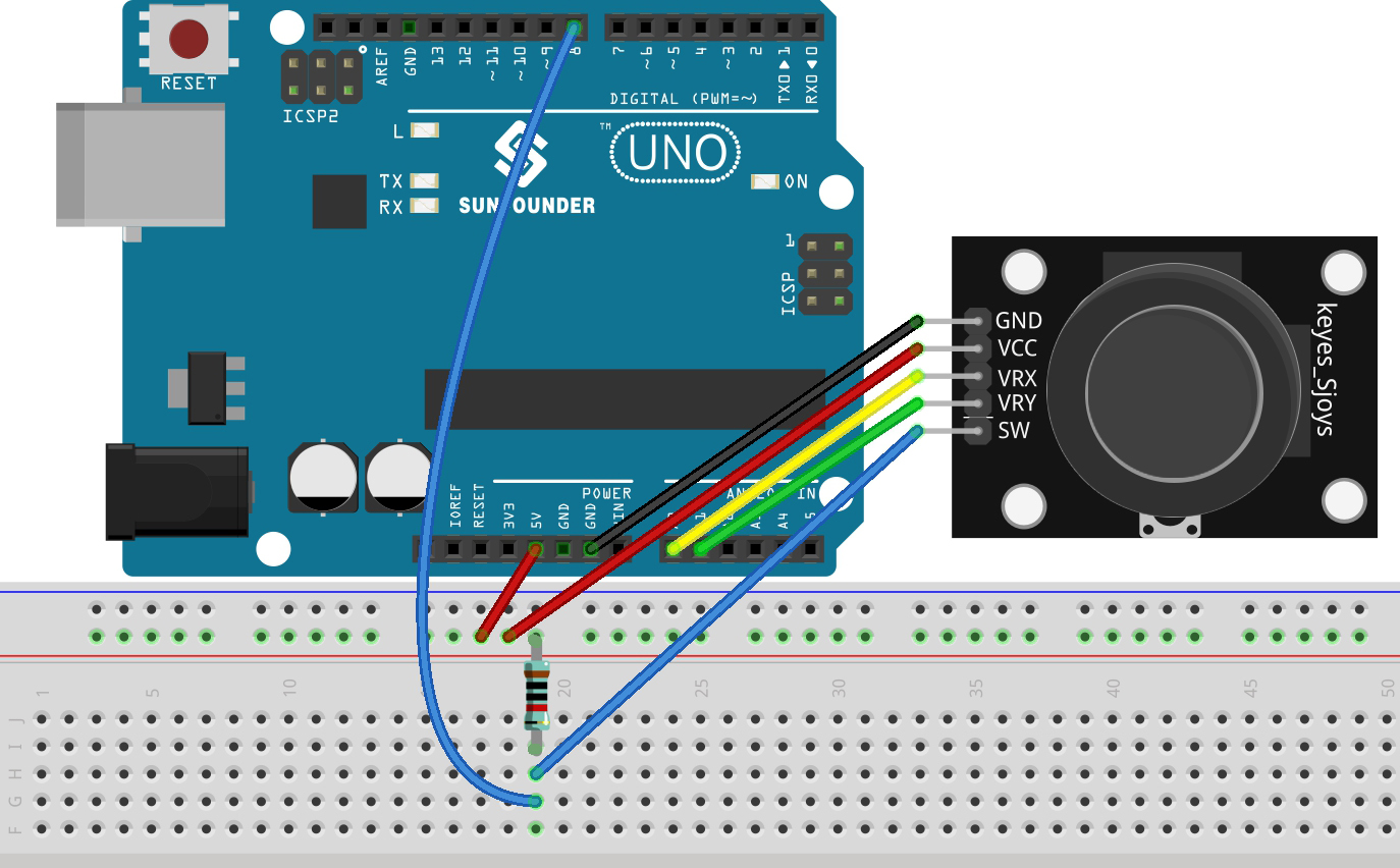
Wiring
Code
Note
Open the
4.3.toggle_the_joystick.inofile under the path of3in1-kit\basic_project\4.3.toggle_the_joystick.Or copy this code into Arduino IDE.
Or upload the code through the Arduino Web Editor.
Open the serial monitor after the code has been uploaded successfully to see the x,y,z values of the joystick.
The x-axis and y-axis values are analog values that vary from 0 to 1023.
The Z-axis is a digital value with a status of 1 or 0 ( when pressed , it is 0 ).