Note
Hello, welcome to the SunFounder Raspberry Pi & Arduino & ESP32 Enthusiasts Community on Facebook! Dive deeper into Raspberry Pi, Arduino, and ESP32 with fellow enthusiasts.
Why Join?
Expert Support: Solve post-sale issues and technical challenges with help from our community and team.
Learn & Share: Exchange tips and tutorials to enhance your skills.
Exclusive Previews: Get early access to new product announcements and sneak peeks.
Special Discounts: Enjoy exclusive discounts on our newest products.
Festive Promotions and Giveaways: Take part in giveaways and holiday promotions.
👉 Ready to explore and create with us? Click [here] and join today!
2.4 Rainbow Light
In this project, we will make the RGB LEDs display a rainbow of colors.
RGB LED is equivalent to encapsulating Red LED, Green LED, Blue LED under one lamp cap, and the three LEDs share one cathode pin. Since the electric signal is provided for each anode pin, the light of the corresponding color can be displayed. By changing the electrical signal intensity of each anode, it can be made to produce various colors.
Wiring
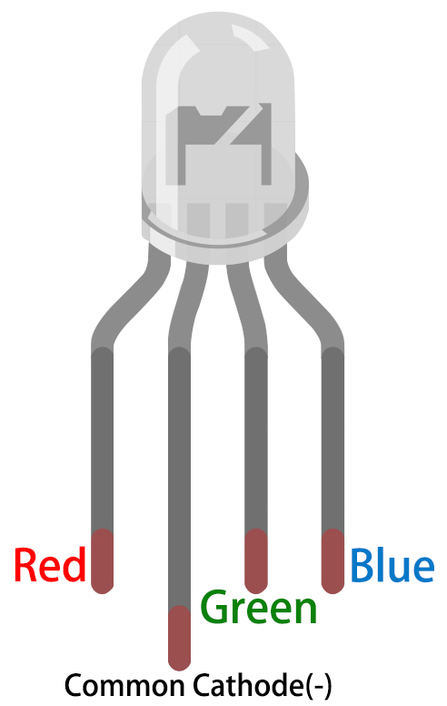
An RGB LED has 4 pins: the longest pin is the common cathode pin, which is usually connected to GND, the left pin next to the longest pin is Red, and the 2 pins on the right are Green and Blue.
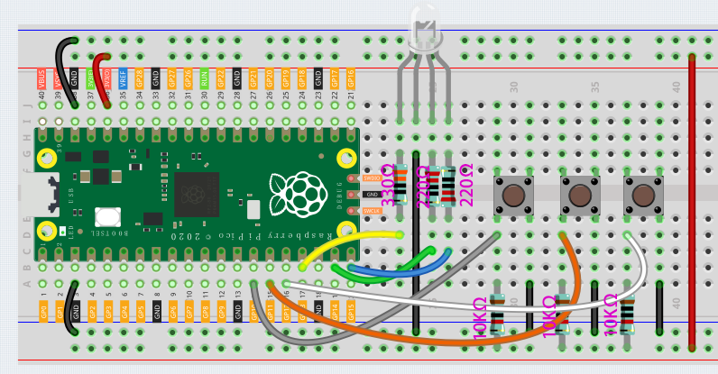
When using the same power supply intensity, the Red LED will be brighter than the other two, and a slightly larger resistor(330Ω) needs to be used to reduce its brightness.
The 3 buttons are used to control the lighting of the Red, Green and Blue LEDs respectively.
Code
Note
You can refer to the image below to write code by dragging and dropping.
Import
2.4_rainbow_light.pngfrom the path ofeuler-kit\piper. For detailed tutorials, please refer to Import the Code.
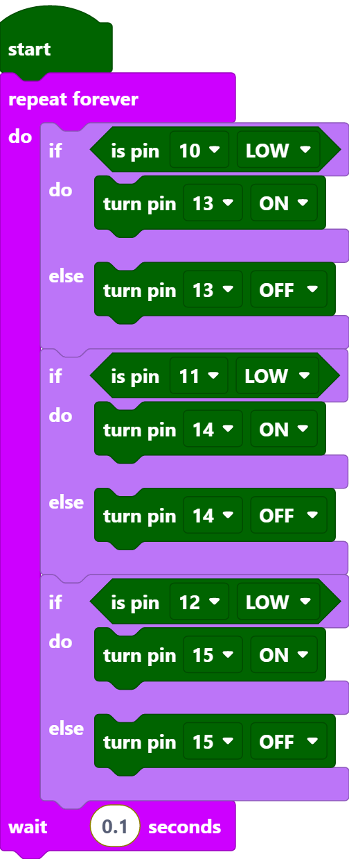
After connecting Pico, click the Start button and the code starts to run. Pressing these buttons individually will emit a single color of light, but if two of the buttons are pressed at the same time, or all 3 buttons are pressed at the same time, the RGB LEDs will emit a variety of different colors, up to a maximum of 7.
Note
In fact, RGB LED can emit up to 16 million colors, but since Piper Make does not have a block to output PWM signal, here we just use the [turn pin() (ON/OFF)] block to make RGB LEDs show 7 colors.
How it Works?
You can think of this project as using three buttons to control the RGB LED, and setting three if judgment conditions to determine whether the three buttons are pressed or not. When the buttons are pressed, the levels of the corresponding pins are pulled high, causing the RGB LED to display different colors.