2.2 Colorful Light
As we know, light can be superimposed. For example, mix blue light and green light give cyan light, red light and green light give yellow light. This is called “The additive method of color mixing”.
Based on this method, we can use the three primary colors to mix the visible light of any color according to different specific gravity. For example, orange can be produced by more red and less green.
In this chapter, we will use RGB LED to explore the mystery of additive color mixing!
RGB LED is equivalent to encapsulating Red LED, Green LED, Blue LED under one lamp cap, and the three LEDs share one cathode pin. Since the electric signal is provided for each anode pin, the light of the corresponding color can be displayed. By changing the electrical signal intensity of each anode, it can be made to produce various colors.
Required Components
In this project, we need the following components.
It’s definitely convenient to buy a whole kit, here’s the link:
Name |
ITEMS IN THIS KIT |
LINK |
|---|---|---|
3 in 1 Starter Kit |
380+ |
You can also buy them separately from the links below.
COMPONENT INTRODUCTION |
PURCHASE LINK |
|---|---|
Schematic
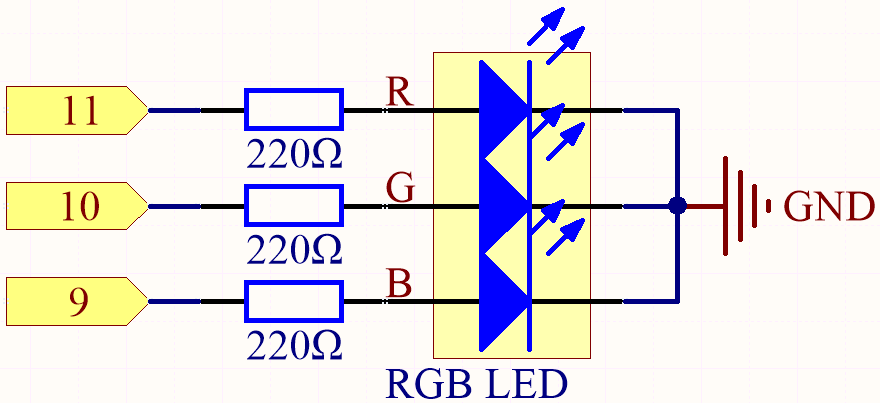
The PWM pins 11, 10 and 9 control the Red, Green and Blue pins of the RGB LED respectively, and connect the common cathode pin to GND. This allows the RGB LED to display a specific color by superimposing light on these pins with different PWM values.
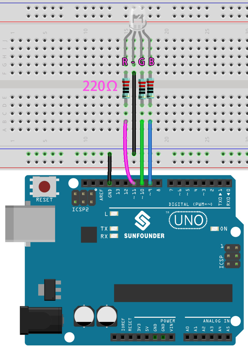
Wiring
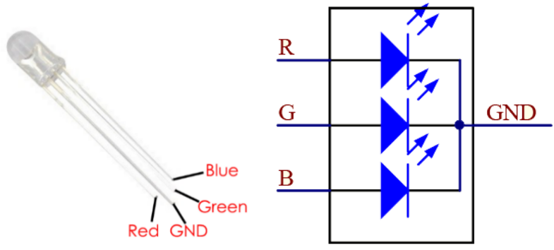
An RGB LED has 4 pins: the longest pin is the common cathode pin, which is usually connected to GND, the left pin next to the longest pin is Red, and the 2 pins on the right are Green and Blue.
Code
Here, we can choose our favorite color in drawing software (such as paint) and display it with RGB LED.
Note
You can open the file
2.2.colorful_light.inounder the path of3in1-kit\basic_project\2.analogWrite\2.2.colorful_light.Or copy this code into Arduino IDE.
Or upload the code through the Arduino Web Editor.
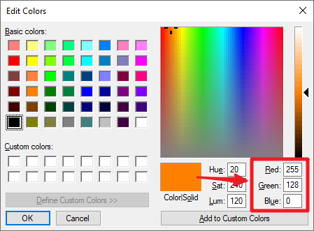
Write the RGB value into color_set(), you will be able to see the RGB light up the colors you want.
How it works?
In this example, the function used to assign values to the three pins of RGB is packaged in an independent subfunction color().
void color (unsigned char red, unsigned char green, unsigned char blue)
{
    analogWrite(redPin, red);
    analogWrite(greenPin, green);
    analogWrite(bluePin, blue);
}
In loop(), RGB value works as an input argument to call the function color() to realize that the RGB can emit different colors.
void loop()
{
    color(255, 0, 0); //  red
    delay(1000);
    color(0,255, 0); //  green
    delay(1000);
    color(0, 0, 255); //  blue
    delay(1000);
}