Note
Hello, welcome to the SunFounder Raspberry Pi & Arduino & ESP32 Enthusiasts Community on Facebook! Dive deeper into Raspberry Pi, Arduino, and ESP32 with fellow enthusiasts.
Why Join?
Expert Support: Solve post-sale issues and technical challenges with help from our community and team.
Learn & Share: Exchange tips and tutorials to enhance your skills.
Exclusive Previews: Get early access to new product announcements and sneak peeks.
Special Discounts: Enjoy exclusive discounts on our newest products.
Festive Promotions and Giveaways: Take part in giveaways and holiday promotions.
👉 Ready to explore and create with us? Click [here] and join today!
Hardware Introduction
Specification Table
Parameter |
Min |
Typical |
Max |
Unit |
Battery Shutdown Current |
- |
- |
60 |
uA |
Battery Quiescent Current |
- |
25 |
- |
mA |
DC-DC Output Voltage |
5.1957 |
5.2855 |
5.3766 |
V |
DC-DC Over Temperature Protection |
- |
150 |
- |
℃ |
Battery Charging Current |
- |
- |
1 |
A |
Charging Over Temperature Protection |
- |
135 |
- |
℃ |
Input Low Voltage Switching Threshold |
4.54 |
4.63 |
4.72 |
V |
Balancing Current |
- |
40 |
- |
mA |
Balancing Activation Voltage |
- |
4.1 |
- |
V |
Overview Diagram

Power Input: External power input, can directly power Raspberry Pi while charging the battery.
Default ON/OFF: Select whether to automatically start when the external power input is plugged in during the shutdown state.
SDSIG: Shutdown signal, connecting pin 26 to the middle pin with a jumper cap connects SDSIG to GPIO26 on the Raspberry Pi. Once configured, if the Raspberry Pi shuts down, GPIO26 goes high, signaling PiPower 3 to power off.
BTN: External power button jumper, used for external power button.
PWR LED: Output status LED, lights up when output is activated.
BAT LED: The LED lighting up indicates that the battery is currently supplying power. At this time, you need to monitor the battery level to prevent damage due to over-discharge.
Power Button: Onboard power button for controlling the board’s power:
Single press: Activates output.
Hold for 2 seconds, until the middle two battery LEDs light up then release: Sends shutdown request via i2c.
Continue holding for more than 5 seconds: Directly turns off output.
Battery Indicators: Indicates battery level and charging status.
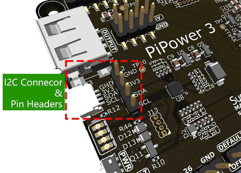
I2C Connector: SH1.0 4P terminal, compatible with qwIIC and STEMMA QT.
I2C Pin Headers: 1x4P 2.54 pin headers.
Type A Output: 5V output interface.
5V/GND Pin Headers: 2 x 4P 2.54 pin headers.
Pin Headers for RPi: Raspberry Pi pin headers, directly connects to the Raspberry Pi.
Battery Connector: XH2.54 3P battery connector.
Warning LEDs: If the battery is reversed, two red LEDs light up, warning of battery reversal.
Power Button

Onboard power button for controlling the board’s power:
Single press: Activates output.
Hold for 2 seconds, until the middle two battery LEDs light up then release: Sends shutdown request via i2c.
Continue holding for more than 5 seconds: Directly turns off output.
Battery Indicators
Four onboard LEDs indicate battery level and charging status. Note, if charging during shutdown, the indicator light will still display the charging status until charging is complete.

4 LEDs lit: Battery >80%
3 LEDs lit: 60%< Battery <80%
2 LEDs lit: 40%< Battery <60%
1 LED lit: 20%< Battery <40%
First LED flashing: Battery <20%
LEDs incrementally light up in a cycle: Charging
Middle two LEDs flashing: Waiting for shutdown signal
All LEDs off: Unpowered or in sleep mode
Power Input

If using on Raspberry Pi, the power input should use a USB PD source supporting 5V/3A, like the official Raspberry Pi 27W power source (recommended). Otherwise, under high power consumption, the battery may not charge or may even deplete until the battery can no longer supply power.
The BAT LED can confirm whether the battery is currently supplying power externally to ensure battery safety so that the battery remains powered in case of a power outage, acting as a UPS.

Power Path
PiPower 3 integrates power path functionality, automatically switching power paths to reduce battery wear and seamlessly switch power.
With external power connected, 5V output is directly from the external 5V, which can be switched off. If conditions allow, external power also charges the battery (see charging current).
When power is disconnected, the system automatically switches to battery step-down output for power, seamlessly switching to protect the system during a power outage.
BAT LED can confirm whether the battery is currently supplying power externally.
Battery Connector
XH2.54 3P battery connector.

MCU I2C Communication
I2C address: 0x5a
The onboard MCU collects various signals from the board and stores them in registers, which can be accessed via I2C.
Set Register Table:

Default ON/OFF
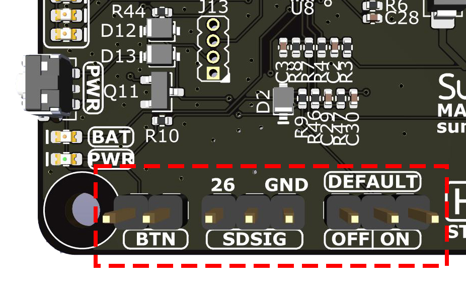
This ON/OFF jumper is used to select: whether the output is defaultly activated when USB power is plugged in after shutdown.
If the jumper cap is on the left, connected to OFF, then inserting USB power after shutdown will not activate the output.
If the jumper cap is on the right, connected to ON, then inserting USB power after shutdown will activate the output.
This feature is typically used for devices that need to be defaultly on, such as private servers: when there is a power outage outside, PiPower 3 instructs the Raspberry Pi to shutdown. Waiting for the next power supply, PiPower 3 automatically activates the output, turning on the Raspberry Pi, thus eliminating the need for manual operation.
This function can also be used as a remote on/off feature. Connect the input to a smart plug or smart switch. Set the Shutdown Percentage to 100%. When remote shutdown is needed, directly control the smart plug to cut power, PiPower 3 detects the power outage, notifies the Raspberry Pi to shutdown, then cuts power. When remote power-on is needed, directly turn on the smart switch, PiPower detects power, defaults to power-on, and can start the Raspberry Pi, achieving remote control of power on and off.
BTN
This BTN jumper is for an external power button. If you need to install PiPower 3 inside a casing, you might not be able to press the onboard power button. At this time, you need an external button to switch power on and off. Connect a self-recovering switch to the jumper, which can be a tactile switch or a vintage metal button. After connecting, you can press the external button just like the onboard button.
SDSIG
The SDSIG shutdown signal involves three pins: pin 26, a middle pin, and a right-side GND pin.
If you connect pin 26 to the middle pin using a jumper cap, SDSIG will connect to GPIO26 on the Raspberry Pi. After configuration, if the Raspberry Pi shuts down, the GPIO26 pin will be pulled high, indicating that SDSIG is at a high level, signaling PiPower 3 to power off.
If this function is not needed, such as with a single-board computer like Arduino or Raspberry Pi Pico, the jumper cap should be connected to GND.
SDSIG is the shutdown signal pin. Pulling this pin high indicates the host is shut down and needs to be powered off. Pulling it low indicates the host is powered on. If this function is not needed, such as with a single-board computer like Arduino or Raspberry Pi Pico, the jumper cap should be connected to GND. If using a Raspberry Pi, connect the jumper cap to pin 26, install pipower3 software on the Raspberry Pi, and when the Raspberry Pi shuts down, it will pull this pin high, signaling PiPower 3 to power off.
Pin Headers for RPi
Raspberry Pi pin headers, directly connects to the Raspberry Pi, including I2C and power, see Raspberry Pi pin diagram. Headers can be used to stack HATs, but note that I2C and pin 26 are connected.

Raspberry Pi |
MCU On Board |
|---|---|
SDA |
SDA |
SCL |
SCL |
GPIO26 |
SHUTDOWN |
ID_SD |
ID_EEPROM SDA |
ID_SC |
ID_EEPROM SCL |