Features
Pass Through Charging
Shutdown Current:< 0.5mA
Input:
USB Type-C, 5V/3A
Battery Input
Output:
USB Type-A, 5V/3A
2x4P P2.54 pin headers
Charging Power:5V/2A
Equipped Battery
Type: 3.7V Lithium-ion batteries x 2
Capacity: 2000mAh
Connector: PH2.0, 3P
Over Discharge Protection Voltage:6.0V
Overcharge Protection Voltage:8.4V
Dimension: 90mm x 60mm x 24.9mm
On-board Indicators
1 x Charging Indicator (CHG)
1 x Power Indicator (PWR)
4 Battery Indicators (D4 ~ D7)
On-board Power Switch
On-board MCU ESP32 S2
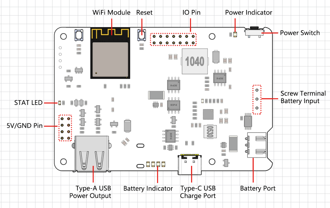
Detailed Introduction
STAT LED
The STAT LED is the status indicator for the ESP32 S2.
Off: ESP32 S2 is powered off.
Slow blinking: ESP32 S2 is powered on, but Wi-Fi is not connected.
Steady on: ESP32 S2 is powered on and Wi-Fi is connected.
Note
The so-called “ESP32 S2 powered off” state refers to the situation when the USB Type C power is connected. In this state, the ESP32 S2 is technically “powered off” but not completely shut down. The power LED still requires the ESP32 S2 to control its illumination, and some functions may remain operational. However, when you unplug the USB Type C power, the ESP32 S2 will shut down completely.
Switch Power Path
PiPower Pro integrates a power path function that automatically switches power paths to ensure maximum output protection.
When external power is connected, the 5V output is directly supplied through the external USB Type C and can be turned off using the switch. The external power source charges the battery with as much current as possible (see charging current) while ensuring the input voltage is greater than 4.6V.
In the moment of power disconnection, the system automatically switches to battery power output with seamless transition, ensuring the system can function properly during power interruptions.
If the external power is below 4.6V, the system automatically switches to battery backup power to prevent external devices from losing power.
Switch |
External Power |
Output Status |
|---|---|---|
On |
Plugged in |
External Power |
On |
Unplugged or voltage below 4.6V |
Battery Power |
Off |
Plugged in |
Off |
Off |
Unplugged or voltage below 4.6V |
Off |
Charging Power
Under the power-on state, the charging current will automatically adjust based on the input voltage.
Switch |
Charging Current |
|---|---|
On |
Adjusted based on input voltage |
Off |
2A |
When the switch is in the “Off” state, PiPower Pro does not supply power externally, and the charging current reaches a maximum of 2A, allowing for fast charging. The charging time from 0% to 100% is approximately 2 hours and 10 minutes.
In the “On” state, since PiPower Pro needs to supply power externally, the external USB also needs to provide power to the battery. To ensure the voltage of the USB power supply remains stable, the charging current is adjusted based on the input voltage, ensuring the voltage stays above 4.6V.
Over-discharge Protection
When the single battery voltage is below 3V, the battery protection activates and the battery is no longer discharged.
When the battery is unplugged, due to the mechanism of the on-board over-discharge protection circuit, the voltage will be considered too low, thus activating the protection circuit; when you replug the battery into the PiPower, the battery will not work properly, at this time, you need to plug the Type C cable into the charging port to turn off the protection circuit, and the battery can be used normally.
Overcharge Protection
Charging ends when the total battery voltage reaches 8.4V.
Charge Balance
When the voltages of the two batteries are not equal, the charging current of the two batteries is automatically adjusted to balance the two batteries.
When a single battery exceeds 4.2V, the voltage divider resistor channel conducts and the battery charging current is reduced or even discharged.
Battery
The product comes with two 3.7V 18650 lithium-ion batteries in series, featuring an XH2.54 3P connector, with a nominal capacity of 2000mAh.
Composition: Li-ion (Lithium-ion)
Capacity: 2000mAh, 14.8Wh
Weight: 90.8g
Cells: 2
Connector: XH2.54 3P
Overcharge Protection Voltage: 4.2V per cell
Over-discharge Protection: 3V
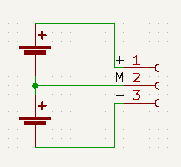
External Battery
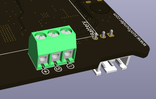
You can connect your own battery using the Screw Terminal. The device only supports two 3.7V lithium-ion or lithium-polymer batteries. It’s preferable for the batteries to have a protection board and ensure an output of more than 15W.
Warning
Do not connect the external battery and the included battery at the same time!
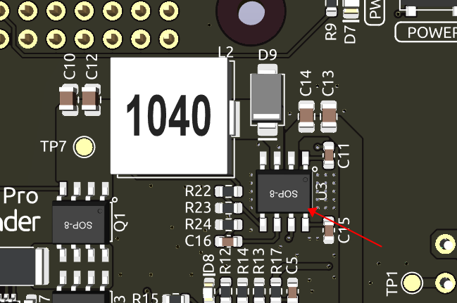
Temperature
When the output power reaches the maximum nominal 5V/3A, the temperature of DC-DC buck chip U1 will rise to about 70-80 degrees Celsius, so be careful not to touch it to prevent burns and keep ventilation. When the temperature reaches the DC-DC protection temperature of 75 degrees Celsius, the DC-DC will shut down to prevent overheating damage.
D8 LED
The D8 LED is a charging status indicator provided by the IP2326 charging chip. Originally, this light was designed to indicate both the charging status and any abnormalities with the battery. However, it can only detect if there’s current flow in the charging output. This output current can be routed through a DC-DC converter to output 5V. In simpler terms, when there’s insufficient input power, the battery will supplement the power supply, and during this, the LED remains steadily lit, which can be misleading. However, the LED was retained as it can indicate if the battery is functioning normally (the LED will blink if the battery isn’t inserted).
Battery Indicators
The relationship between the battery indicators and voltage is as follows:
4 LEDs all on: voltage > 7.7V
3 LEDs on: voltage > 7.2V
2 LEDs on: voltage >6.7V
1 LED on: voltage > 6.4V
4 LEDs all off: voltage <6V,at this time,batteries need to be charged.