Pico RDP
Introduction
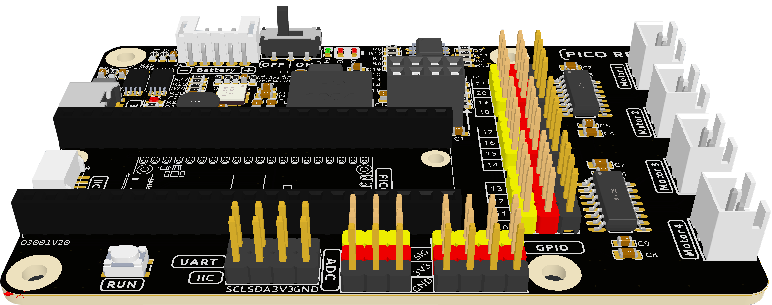
The Pico Robotics Development Platform (RDP) is a Wi-Fi extension module for the Raspberry Pi Pico designed by SunFounder.
It uses the ESP01S module as a WiFi communication module for various remote control situations.
There are 12 channels of PWM pins, 3 channels of ADC pins, and 4 channels of GPIO pins reserved on this Pico RDP.
The Pico RDP also integrates two motor driver chips - TC1508S, which can drive 4 motors simultaneously.
Further, the Pico RDP has integrated battery charging circuitry, so you can plug in a 5V/2A USB-C cable directly to charge the included battery, which takes 130 minutes to fully charge.
Pico RDP Pinout
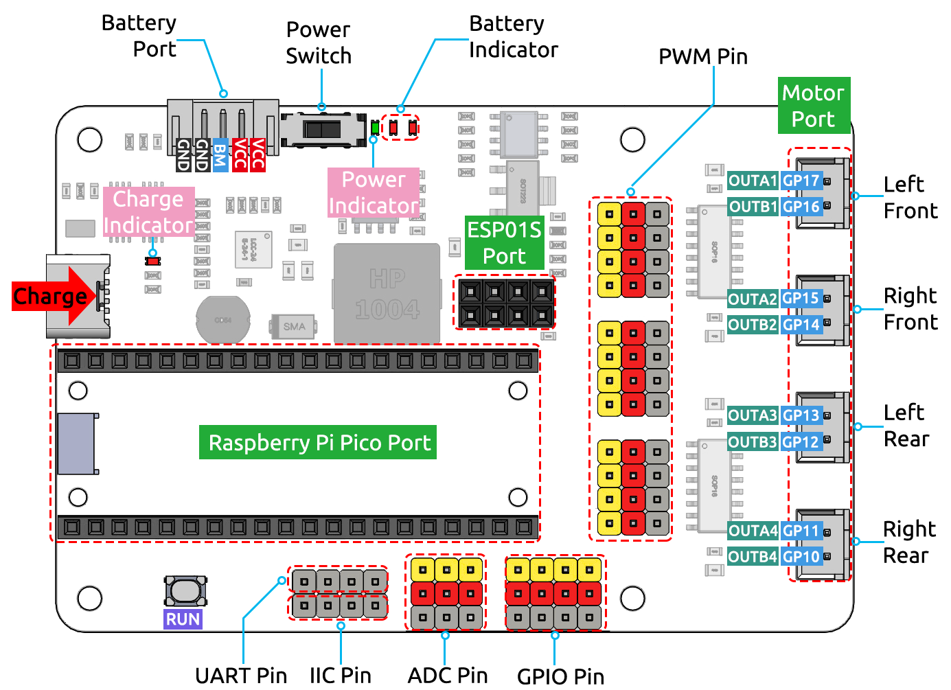
- 3 groups of indicators.
Charge Indicator: This indicator lights up after plugging in the USC-C cable for charginge.
Power Indicator: Turn the power switch to ON, the power indicator will light up.
Battery Indicators: Two indicators represent different power levels. When both battery indicators are off, you need to use the USB-C cable to charge. When charging, these two indicators will flash.
- Battery Port:
6.6V ~ 8.4V PH2.0-5P power input.
Powering the Pico RDP and Raspberry Pi Pico at the same time.
- Power Switch
Slide to ON to power on the Pico RDP.
- Motor Port
4 groups of motor ports.
- Charge Port
After plugging into the 5V/2A USB-C cable, it can be used to charge the battery for 130min.
- ESP01S Port
Used to plug in the ESP01S module.
- Raspberry Pi Pico Port
This connector is used to plug in the Raspberry Pi Pico, with the micro USB port facing outward.
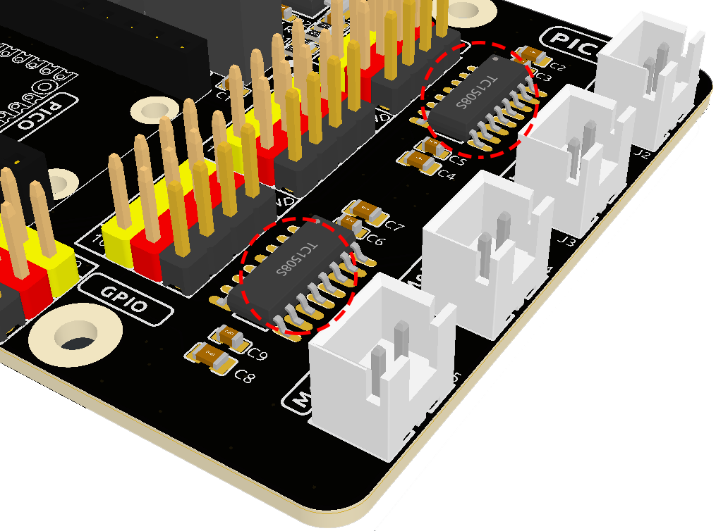
Motor Port
There are four motor connectors on the Pico RDP, controlled by two TC1508S motor driver chips, which operate over a wide voltage range of 2.2 to 5.5V, with a maximum continuous output current of 1.8A.
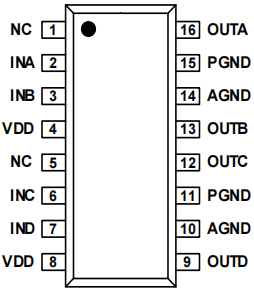
The following is a table of the input and output logic of the TC1508S chip.
Input |
Output |
Status |
||||||
INA |
INB |
INC |
IND |
OUTA |
OUTB |
OUTC |
OUTD |
|
L |
L |
Hi-Z |
Hi-Z |
Standby |
||||
H |
L |
H |
L |
Rotate |
||||
L |
H |
L |
H |
Reverse direction of rotation |
||||
H |
H |
L |
L |
Stop |
||||
L |
L |
Hi-Z |
Hi-Z |
Standby |
||||
H |
L |
H |
L |
Rotate |
||||
L |
H |
L |
H |
Reverse direction of rotation |
||||
H |
H |
L |
L |
Stop |
Two TC1508S chips are used here to drive the four motors, and the corresponding schematic is shown below.
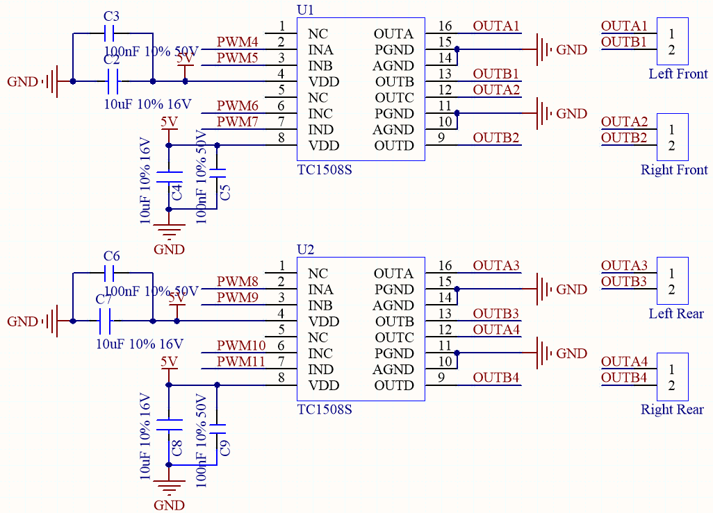
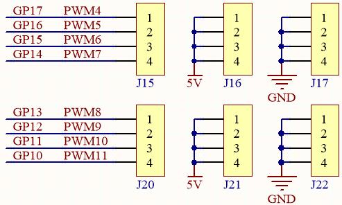
So the corresponding control pins of the 4 motor interfaces are shown below.
Raspberry Pi Pico |
Pico RDP |
GP17 |
OUTA1 |
GP16 |
OUTB1 |
GP15 |
OUTA2 |
GP14 |
OUTB2 |
GP13 |
OUTA3 |
GP12 |
OUTB3 |
GP11 |
OUTA4 |
GP10 |
OUTB4 |